Why Do Temperature Control Systems Fail In Industry?
A temperature control system fails due to sensor drift, bad PID tuning, and relay wear, which halts critical industrial production.
Crucial Vulnerabilities in Any Industrial Temperature Control System
Modern manufacturing plants rely heavily on automated machinery to maintain specific thermal ranges. A reliable temperature control system prevents production disasters in chemical processing plants. Without proper maintenance, these machines eventually fail during crucial operations. Engineers often overlook early warning signs like minor voltage fluctuations. Such minor issues quickly escalate into complete hardware breakdowns. Unexpected thermal spikes damage raw materials and halt assembly lines. Extreme thermal degradation costs companies thousands of dollars in lost productivity every hour. Technicians must monitor these setups closely to avoid catastrophic equipment damage. Regular audits help identify weak electrical connections before they cause total failure. Consistent temperature regulation ensures product consistency across all manufacturing batches.
")
")
Calibration Drift in Thermal Regulation Setup
Industrial environments present extreme challenges to delicate measurement instruments. Sensors like Pt100 RTDs and thermocouples experience physical stress from constant heating cycles. Over time, protective sheaths corrode due to chemical exposure in the air. Physical decay changes the internal resistance of the sensor wire. Consequently, the device sends inaccurate electrical signals to the central processor. Even a tiny calibration drift of two degrees ruins sensitive chemical reactions. Operators fail to notice this gradual decline until product batches fail quality tests. Regular testing against certified reference standards prevents this specific failure mode. Engineers must replace degraded probes before they corrupt the entire feedback loop. Clean air and proper vibration isolation extend the life of these sensors.
Controller Tuning and Signal Interference Issues
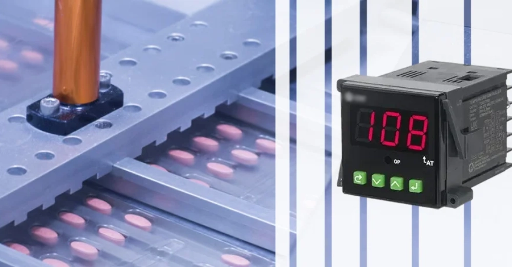
Microprocessors calculate output values based on complex mathematical algorithms. Incorrect proportional, integral, and derivative parameters cause severe temperature oscillations. Technicians sometimes enter wrong values during initial setup phases. Electromagnetic interference from nearby high-voltage lines also disrupts fragile communication signals. Shielded cables block this unwanted noise and protect data integrity. Selecting the correct unit, like a Temperature Controller for Dry type Transformer, resolves specific hardware mismatch issues. Specialized devices handle high electrical noise environments without losing accuracy. Implementing an advanced temperature control system reduces overshoot during critical heating phases. Proper tuning prevents unnecessary strain on the heating elements. Smart controllers automatically adjust parameters when process demands shift unexpectedly. Predictive algorithms also help maintain thermal stability.
Component Wear in Heat Management Setup
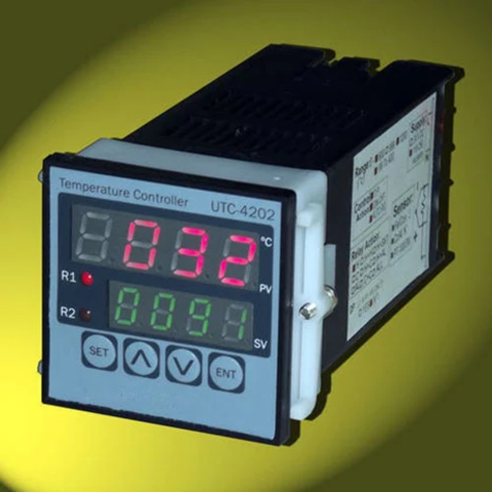
Heavy duty actuators translate electrical commands into physical heating or cooling actions. Solid State Relays often overheat when ventilation fans fail in control cabinets. Silicon Controlled Rectifiers degrade under continuous high current loads. Mechanical contactors suffer from arc damage during frequent switching cycles. Using a WK Dial-Type Temperature Controller for Cabinets offers reliable protection in compact spaces. Analog units operate independently of digital processor networks. Dust accumulation on heat sinks prevents proper thermal dissipation. High temperatures inside the enclosure accelerate the aging of internal capacitors. Technicians must inspect electrical terminals for signs of heat discoloration. Loose terminal screws increase resistance and generate dangerous localized heat. Regular maintenance schedules prevent sudden component failures in these demanding environments.
Breakdown of Common Industrial Thermal Failure Points
| Component | Common Failure Mode | Root Cause | Industrial Impact |
|---|---|---|---|
| RTD Sensor | Calibration Drift | Physical Vibration | Inaccurate Readings |
| PID Controller | Software Lockup | Voltage Fluctuations | Loss of Control |
| Solid State Relay | Short Circuit | Excessive Heat | Continuous Heating |
Analysis of Common System Component Failures
Industrial facilities face severe losses when a temperature control system component fails due to high heat. Each row in the above table represents a critical path in the automated regulation process. For example, RTD drift causes the controller to receive misleading temperature feedback. Processor calculations then increase power to the heaters based on incorrect data. Such action creates an accidental thermal runaway situation in chemical reactors. Similarly, a shorted solid state relay bypasses all digital safety shutoffs. Current flows continuously to the heating elements regardless of controller instructions. Technicians must analyze these failure modes to develop effective preventative maintenance schedules. Proper analysis of these electrical relationships helps maintenance teams isolate faults rapidly. Fast troubleshooting minimizes expensive process downtime during critical production runs.

Comparison of System Maintenance Indicators
| Indicator Parameter | Normal Range | Critical Limit | Required Action |
|---|---|---|---|
| Sensor Resistance | 100 - 138 Ohms | > 150 Ohms | Recalibrate Probe |
| Relay Temperature | 30 - 55 Celsius | > 80 Celsius | Clean Heat Sink |
| Controller Voltage | 24 Volts DC | < 21 Volts DC | Check Power Supply |
Interpretation of Thermal Performance Indicators
Monitoring resistance values and cabinet temperatures prevents sudden hardware failure. Data in the second table highlights the importance of keeping components within designated safe limits. When sensor resistance exceeds normal levels, calibration errors occur immediately. Similarly, a hot relay indicates poor heat dissipation within the electrical cabinet. High temperatures dry out the thermal grease behind the semiconductor switch. Such dryness reduces thermal conductivity and triggers rapid component degradation. Technicians must use thermal imaging cameras to locate hot spots on electrical terminals. Voltage drops below twenty-one volts cause the digital processor to reboot randomly. Frequent power cycles disrupt the execution of safety programs. Addressing minor parameter shifts early protects the entire industrial process from sudden shutdown.
Essential Checklist for Temperature Regulation Unit
- Tighten all terminal screws to prevent high-resistance connections.
- Apply fresh thermal grease to solid state relay heat sinks.
- Verify sensor calibration using a dry-well calibrator.
- Measure output voltage from the central control power supply.
- Inspect cabinet ventilation fans for correct rotation and airflow.
Detailed Execution of Maintenance Protocols
Executing each step in the list ensures the reliability of automated production machinery. Loose terminal screws generate localized heat that burns delicate wire insulation. Applying thermal grease creates a reliable path for excess heat to escape. Technicians must verify sensor accuracy under real operating conditions. Dry-well calibrators provide stable temperatures for precise resistance comparison. Slight voltage drops trigger unexpected software restarts during heavy production hours. Clean cabinet fans keep air flowing over hot solid state relays. Regular physical inspections identify issues that digital sensors cannot detect. Maintenance teams should record these measurements in a centralized system database. Consistent documentation helps track component wear patterns over long operating periods. Proper execution of these procedures prevents unscheduled downtime in the plant.
Practical Maintenance for a Temperature Control System
Proactive maintenance methodologies keep industrial plants running smoothly without unexpected shutdowns. Maintaining a modern temperature control system requires diligent attention to every component. Technicians must combine visual inspections with precise digital diagnostic testing. Replacing worn parts before they fail saves companies high emergency repair costs. Furthermore, accurate calibration ensures compliance with international quality standards. Plant managers should invest in high-quality diagnostic tools for their maintenance staff. Training technicians to spot early warning signs prevents minor issues from escalating. Regular cleaning schedules keep delicate electronics free from conductive dust. Ensuring stable input voltage protects digital microprocessors from sudden program failures. Ultimately, systematic thermal care guarantees long-term manufacturing success and product quality. Dedicated maintenance teams extend the operating life of expensive heavy machinery.
")
FAQ
How often should industrial sensors undergo calibration?
Industrial facilities must calibrate thermal sensors at least once every six months. Harsh operating conditions accelerate sensor degradation and increase measurement errors. Vibration from heavy machinery also destabilizes internal electronic alignments over time. Chemical exposure in food or pharmaceutical plants requires even more frequent testing. Operators should run validation cycles quarterly to guarantee regulatory compliance. Proper documentation of these tests helps identify long-term accuracy trends. Replacing drifting components early prevents expensive product waste during manufacturing runs. Regular maintenance keeps automated production lines running efficiently and safely throughout the year. Dedicated technicians usually execute these calibration tasks during scheduled weekend shutdowns.
What indicates a failing solid state relay?
A failing solid state relay usually exhibits clear physical and electrical symptoms. Technicians often notice excessive heat buildup on the external protective casing. Visual inspection reveals scorched plastic or melted wire insulation near the terminals. Electrically, a damaged relay stays in a permanently closed state. Continuous electrical continuity keeps heaters running even when the controller shuts down. Thermal runaway occurs quickly and threatens overall plant safety. Using high-quality multimeters helps maintenance staff identify these shorts before disasters occur. Installing active cooling fans inside the cabinet prevents premature relay failures from heat stress. Regular monitoring of relay temperatures ensures steady production and keeps workers safe.
Why does improper tuning disrupt thermal processes?
Poorly configured controller settings cause severe temperature fluctuations around the target setpoint. Incorrect settings force heaters to cycle on and off too quickly. Rapid cycling wears out electrical contacts and wastes energy. Furthermore, large temperature overshoots degrade sensitive product batches instantly. Process control loops require precise calculations to maintain narrow temperature bands. Technicians must use systematic tuning methods to find optimal balance. Ignoring these settings leads to unstable operations and eventual hardware breakdowns. Proper tuning ensures smooth transitions and maintains consistent thermal environments. Stable heat levels protect delicate equipment from unnecessary thermal fatigue. Experienced engineers always check controller parameters before starting any major production run.