Can EASI-R Earth Fault Indicator Prevent Electrical Faults?
Enhance medium-voltage grid safety with the easi-r earth fault indicator to actively minimize unexpected power outages and costly downtime.
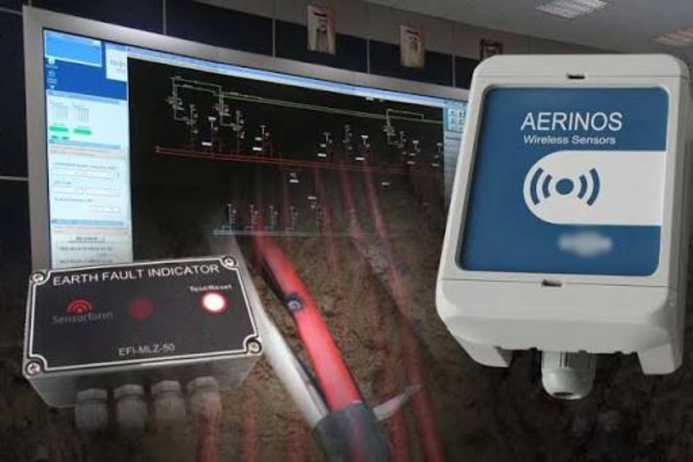
Modern electrical distribution networks experience frequent transient disturbances and ground overcurrent conditions. Unstable grid voltages often damage sensitive industrial machinery and interrupt municipal power delivery. Grid operators require immediate warnings to prevent minor insulation leakage from turning into catastrophic failures. Implementing the easi-r earth fault indicator provides a highly reliable way to monitor these systemic issues. This device detects abnormal current vectors before serious thermal damage occurs across the substation equipment. Maintenance crews can quickly locate weak cable sections by viewing the physical indicators on the line. Prompt isolation of these affected feeder lines stabilizes the remaining local distribution system. Ultimately, proactive monitoring protects expensive infrastructure assets and maintains constant electrical supply to consumers.
Crucial Technical Features of the EASI-R Earth Fault Indicator
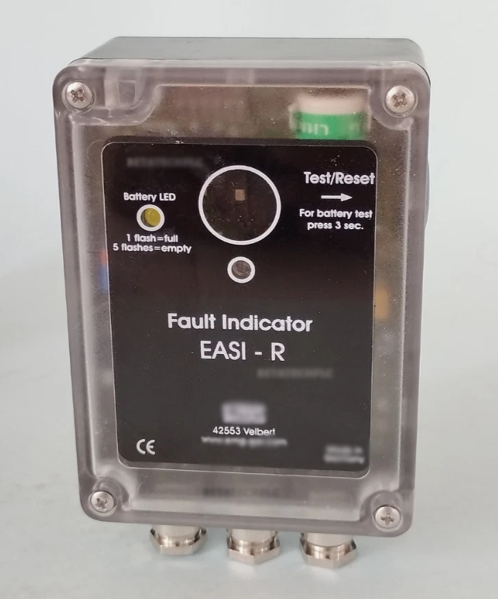
Engineers value specific design attributes when choosing electrical protective devices for municipal subpanels. This physical monitoring unit utilizes a divisible current transformer that fits directly onto screened cables. Retrofitting the sensor does not require cutting existing heavy-duty cables during the installation process. The display unit operates on a replaceable lithium battery with a long service life. Specifically, the system uses a high-capacity lithium thionyl chloride battery providing 3.6 volts. Operators can also choose to utilize an auxiliary power source for continuous system monitoring. If you compare options, a Panel mounted Paddle Type Short circuit Fault Indicator provides different signaling. However, this featured model utilizes a bright LED alongside a mechanical flag for daytime visibility. Highly visible flag systems ensure that field technicians can verify statuses without special diagnostic tools.
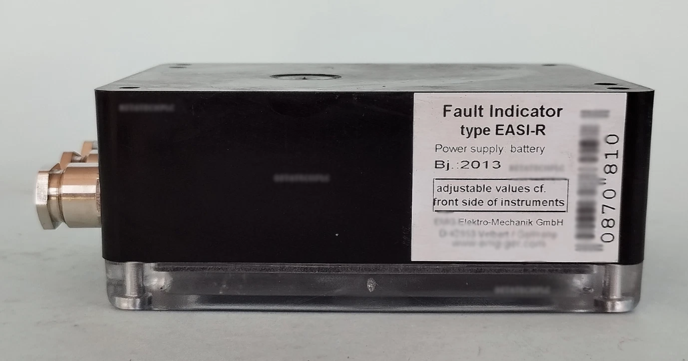
Working Principle of High-Sensitivity Earth Fault Indicators
Superb engineering relies on precise magnetic flux measurement to identify minor electrical leakage within power grids. A physical current transformer continuously measures the vector sum of all three phases. Under normal operating conditions, this sum equals zero because currents remain balanced. An insulation breakdown quickly disrupts this balance, creating a net zero-sequence current. Using the easi-r earth fault indicator allows operators to measure this imbalance accurately. The device features five selectable trip currents ranging from 10 to 160 amperes. Additionally, engineers can configure four response delays between 40 and 300 milliseconds. These adjustments allow the equipment to ignore temporary load changes. Such features prevent false alarms during normal grid switching operations.
| Technical Parameter | Available Range / Value | Application Purpose |
|---|---|---|
| Trip Current Options | 10 A, 20 A, 40 A, 80 A, 160 A | Adapting to varied network loads |
| Response Delay Times | 40 ms, 100 ms, 200 ms, 300 ms | Filtering transient grid switching |
| Battery Specification | Lithium AA 3.6 V (2600 mAh) | Providing long-term standby power |
| Enclosure Protection | IP67 rating standard | Ensuring reliable outdoor placement |
Technical Comparison of Network Protection Instruments
Analyzing these electrical properties reveals the specific design focus of modern distribution protection systems. Adjustable trip currents starting at 10 amperes enable early detection of low-level faults. Operators can increase this threshold to 160 amperes to accommodate larger substation capacities. The four delay settings prevent premature tripping during harmless transient surges or transformer inrush phases. Powering the system with a specialized lithium chemistry ensures uninterrupted service for over twenty years. External casing design employs a rugged IP67 enclosure to withstand heavy rain and dusty conditions. These strict hardware parameters guarantee that monitoring continues even during auxiliary power blackouts. Field technicians can trust these measured values to make quick decisions during emergency repair tasks.
- Flexible power options including high-capacity lithium batteries and external auxiliary connections.
- Visible fault indicators utilizing combined blinking LED lights and mechanical flag displays.
- Integration options with remote SCADA networks using specialized output contacts.
- Divisible current sensors that allow clean installation without breaking existing insulation.
Key Benefits of Deploying Advanced Ground Fault Indicators
Deploying these sophisticated monitoring accessories provides distribution utilities with clear operational benefits. Having flexible power choices means the monitoring device remains active during severe system blackout situations. Technicians rely heavily on the visual duality of mechanical flags and flashing LEDs. This combined indicator system ensures clear daytime visibility from a distance without opening the cabinet. Furthermore, integrating these indicators with SCADA systems allows control centers to receive instant telemetry status updates. Dual remote communication contacts easily transmit real-time alerts to the central control interface. Finally, installing divisible current transformers significantly lowers labor costs during grid modernization projects. Maintenance crews do not need to dismantle heavy cable terminations to secure the sensing hardware.
| Indication Mode | Physical Display Behavior | Grid Event Meaning |
|---|---|---|
| Single LED Flash | Periodic blinking of red diode | Transient or active ground fault detected |
| Double LED Flash | Double rapid blinking sequence | Permanent cable fault in progress |
| Mechanical Flag | Red flag visible in viewing window | Daytime visible trip confirmation |
| No Indication | Dark display and clear window | Normal network operational currents |
How the EASI-R Earth Fault Indicator Prevents Catastrophic Failures
Interpreting these specific optical patterns helps grid operators respond correctly to dangerous network situations. A flashing LED tells operators that an overcurrent event has recently occurred. If a permanent insulation breakdown happens, the double blinking sequence immediately alerts the crew. This allows operators to differentiate between temporary lightning surges and severe cable failures. Utilizing the easi-r earth fault indicator prevents secondary transformer damage by speeding up fault isolation. Additionally, the mechanical flag remains visible even during complete auxiliary power failures. Crews can quickly drive along overhead lines to identify the exact location of the damage. Such rapid physical confirmation minimizes systemic stress across the broader municipal grid. Ultimately, this protective strategy reduces the average duration of local customer power blackouts.
Compliance with International Electrical Engineering Standards
Utility engineers prioritize hardware that complies strictly with international electrical transmission and distribution standards. Reliable testing procedures verify that protection equipment operates safely under massive thermal stresses. The design adheres fully to the well-established IEEE 495 standard for fault indicators. Industry standards guarantee that these physical sensors perform reliably under various environmental challenges. For instance, alternative systems like a Cable Type Short Circuit Grounding Flash Fault Indicator also require precise certification. Choosing standard-compliant hardware prevents dangerous failure modes during high-voltage surge events. Compliance with standard protocols like IEC 61850 also enables integration into modern substation control networks. These open protocols simplify communication between the remote sensor units and the centralized SCADA system.
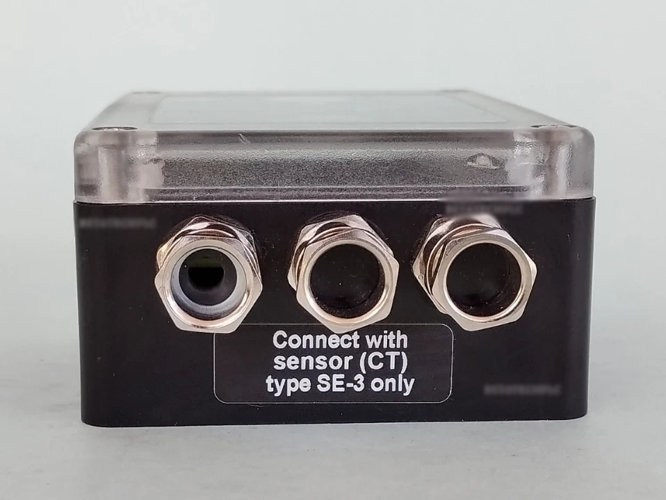
Maximizing Distribution Reliability with Modern Earth Fault Indicators
Maintaining a highly resilient electrical grid requires continuous investment in reliable automated hardware. Modern substation operators cannot rely solely on manual inspection processes during major power disruptions. Installing the easi-r earth fault indicator represents a major step toward building a fully self-healing grid. These advanced sensing units immediately feed vital network diagnostic data directly to substation computerized dashboards. Control engineers can analyze these real-time signals to make smart routing adjustments within seconds. Rapid automated responses prevent minor cable failures from cascading into massive regional blackouts. Ultimately, investing in certified protective hardware enhances overall distribution safety and customer satisfaction metrics. Reliable fault monitoring ensures a stable power supply for essential municipal services.
FAQ
What is the typical lifespan of a lithium battery inside a fault indicator?
The internal lithium thionyl chloride battery provides up to twenty years of reliable standby operation under normal conditions. This outstanding service life depends on the advanced energy-saving design of the microchip circuits. Standby power consumption remains extremely low because the device only draws significant current during actual ground fault events. Active visual flashing or flag deployment will temporarily consume more energy from the internal battery pack. Fortunately, maintenance crews can easily replace the battery without removing the sensor from the line. Using high-quality replacement cells ensures that the system continues to monitor the grid reliably for decades.
How does the device reset after detecting a transient fault?
Operators can configure several automatic and manual reset options depending on system requirements. The unit supports automatic time-delay resets after one, two, four, or eight hours. Additionally, recovering network current or auxiliary voltage can trigger an automatic reset sequence. Maintenance teams can also manually reset the visual flags by pressing the physical test button. Alternatively, remote reset commands can trigger the system through the integrated SCADA contacts at any time. These flexible reset options prevent the system from showing outdated fault warnings to field workers. This design ensures that the monitoring hardware always displays the most current status of your local grid.
Can this indicator distinguish between normal inrush currents and actual faults?
Yes, this monitoring system features an intelligent filtering algorithm to suppress harmless inrush currents. Standard energizing sequences often create high starting currents that could trick less sophisticated equipment. This unit ignores these brief current surges by applying a programmable response delay. Specifically, the internal microcontroller delays trip activation for up to three seconds during network startup. Such delay ensures that only permanent or sustained overcurrent conditions trigger the optical alarm. As a result, utility companies experience fewer costly false alarms during routine maintenance operations. This intelligent suppression technology significantly improves overall system reliability across the entire power distribution network.