How Does An Electric Earthing Switch Controller Work?
Electric earthing switch controller solutions for interlocking, signal control, safety, selection, maintenance, and reliable operation.
What Is an Electric Earthing Switch Controller?
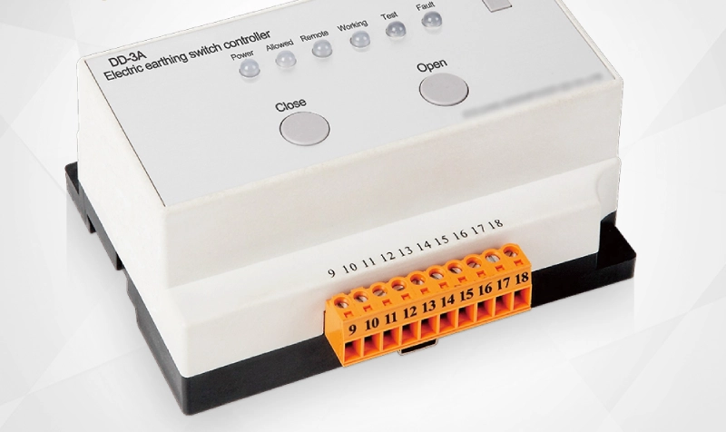
An electric earthing switch controller manages electrical commands for grounding operations inside switchgear systems. It connects control logic with the operating mechanism. The controller receives a local or remote command before initiating an earthing sequence. It then checks relevant permissive conditions through auxiliary contacts and interlocking circuits. If conditions remain valid, the actuator receives the required control signal. Position feedback then confirms whether the grounding switch reached its intended state. This arrangement creates a controlled link between electrical commands and mechanical movement. Medium-voltage switchgear commonly uses such systems for maintenance isolation and grounding procedures. Proper integration also helps operators avoid incorrect switching sequences. Therefore, controller design directly affects operational reliability, signal accuracy, and equipment safety during routine switching activities.
Main Components Inside the Control System
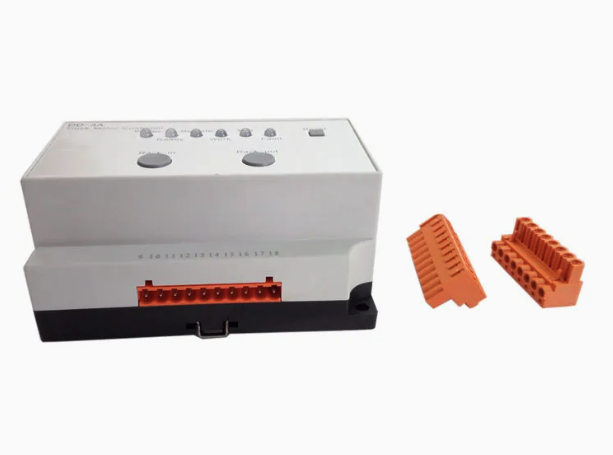
An electric earthing switch controller normally contains several coordinated electrical and electromechanical elements. The control circuit processes operating commands and determines whether the actuator can respond. Relays can provide switching functions, electrical isolation, and logic interfaces. Auxiliary contacts report the mechanical position of the earthing switch. Terminal blocks connect external signals with internal control components. A motor actuator converts electrical energy into mechanical movement when motorized operation applies. Some systems also include indicator circuits for local status confirmation. Remote installations may add communication interfaces for supervisory control. Surge suppression and protective components can help protect control electronics from transient disturbances. Each component serves a specific function, so compatibility matters during system integration. A mismatch in voltage, contact configuration, or actuator requirements can create unreliable operation.
| Component | Primary Function | Typical Role |
|---|---|---|
| Control relay | Switches control circuits | Command processing |
| Auxiliary contact | Reports switch position | Status feedback |
| Motor actuator | Produces mechanical movement | Switch operation |
| Terminal block | Connects field wiring | Signal distribution |
| Interlock circuit | Checks operating conditions | Safety control |
How Does the Operating Sequence Work?
The operating sequence starts when an authorized command reaches the control circuit. The controller first checks whether required permissive signals remain available. These signals can include circuit breaker status, disconnector position, and existing grounding status. When the logic confirms a permitted condition, the output circuit energizes the actuator. The actuator then moves the earthing switch through its mechanical travel. Auxiliary contacts change state as the mechanism reaches the final position. The controller uses these contacts to verify successful operation. If the expected feedback does not arrive, the system can identify an incomplete operation. Timing functions may also detect abnormal movement or stalled mechanisms. This sequence creates a controlled relationship between command input, mechanical action, and electrical confirmation. Such coordination becomes especially important when switchgear supports remote operation or automated switching procedures.
Why Is Electrical Interlocking Important?
Electrical interlocking prevents specific operations when predefined conditions are unsuitable. For example, the control circuit can block grounding commands while another switching device remains in a prohibited state. This function reduces the possibility of conflicting operations during maintenance or switching procedures. Mechanical interlocking provides physical restrictions, while electrical interlocking uses control signals and logic. Many switchgear designs combine both approaches for stronger operational protection. An interlock may depend on auxiliary contacts, relay logic, or signals from another control system. The exact arrangement depends on the switchgear architecture and operating philosophy. Engineers should verify every permissive condition during commissioning rather than testing only the final switch position. Reliable interlocking also requires stable wiring, correctly adjusted contacts, and accurate position feedback. These details help maintain predictable operation throughout the equipment service life.
How Does Position Feedback Improve Reliability?
Position feedback provides electrical confirmation of the earthing switch's mechanical state. Auxiliary contacts commonly generate open or closed signals for the control circuit. The controller can compare the commanded position with the reported position. If both states agree, the system can provide a valid operating indication. A disagreement may indicate incomplete travel, contact failure, wiring problems, or actuator issues. Position feedback also supports remote monitoring because operators cannot directly observe equipment installed in restricted areas. Clear status signals reduce uncertainty during switching procedures. Engineers should verify contact timing and contact ratings when designing feedback circuits. Poorly configured auxiliary contacts can create false indications even when the mechanical mechanism operates correctly. Consequently, feedback quality depends on both mechanical adjustment and electrical signal integrity.
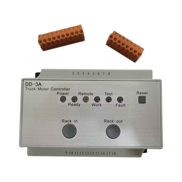
| Signal | Purpose | Possible Abnormal Condition |
|---|---|---|
| Open position | Confirms switch opening | Incomplete travel |
| Closed position | Confirms grounding connection | Contact failure |
| Permissive signal | Allows approved operation | Interlock active |
| Control voltage | Supplies operating circuit | Voltage loss |
| Remote command | Initiates distant operation | Communication fault |
How Does an Electric Earthing Switch Controller Support Safety?
Safety depends on more than simply moving a grounding switch into position. The control system must confirm that the requested operation matches the equipment state. An electric earthing switch controller can coordinate commands, permissive signals, interlocks, and feedback within one operating sequence. This coordination reduces reliance on assumptions during complex switching activities. For maintenance work, accurate grounding status remains particularly important before personnel enter an isolated section. Operators should also verify local indicators instead of depending on a single remote signal. A redundant indication strategy can provide additional confidence where system architecture permits it. Control circuits should use clearly identified terminals and documented wiring diagrams. Regular functional tests can reveal degraded contacts, loose terminals, or abnormal actuator behavior. These practices support safer operation while preserving predictable control performance.
What Signals Should Engineers Monitor?
Engineers should monitor signals that directly affect operation, confirmation, and fault diagnosis. The exact signal list depends on the switchgear design and automation requirements. Common signals include open position, closed position, permissive status, control power, and remote command status. Some installations also monitor actuator running time or fault relay outputs. Remote systems can display these states through supervisory interfaces. Clear signal naming prevents confusion when several switching devices operate within one electrical installation. Signal contacts should also match the voltage and current requirements of the receiving equipment. Shielding and appropriate cable routing may help reduce interference in sensitive control circuits. During commissioning, technicians should test each signal independently and verify its actual mechanical meaning. A complete signal test provides stronger evidence than simply checking whether an indicator lamp changes state.
How Does a Controller Work With Other Switchgear Devices?
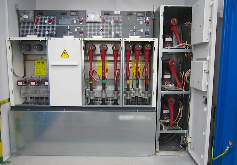
A Controller for Grounding Switch must coordinate with surrounding switchgear equipment when multiple devices share an operating sequence. Circuit breakers, disconnectors, and earthing switches can have defined relationships within the switching logic. For example, the control system may require a circuit breaker to reach a specified state before allowing another operation. Auxiliary contacts provide the electrical information required for these decisions. Relay logic then evaluates whether the requested sequence satisfies the configured conditions. Modern installations may also exchange signals with protection relays or automation systems. Engineers should document these dependencies clearly because an undocumented permissive can complicate troubleshooting. Testing should cover normal sequences, blocked commands, feedback failures, and loss of control power. Such testing verifies the complete interaction rather than focusing on one component alone.
What Factors Influence Controller Reliability?
Environmental and electrical conditions strongly influence long-term controller performance. Temperature changes can affect relay characteristics, terminal connections, and electronic components. Humidity can promote corrosion on contacts and conductive surfaces inside poorly protected compartments. Vibration may gradually loosen terminals or affect mechanical alignment. Control voltage fluctuations can also prevent actuators from completing their required travel. Engineers should therefore match equipment specifications with the actual installation environment. Protection against dust and moisture may become important for outdoor or harsh industrial applications. Periodic inspections should examine wiring, terminals, auxiliary contacts, actuator movement, and indication circuits. Abnormal operating sounds or delayed movement can provide early warning of mechanical problems. Reliable maintenance records also help technicians identify recurring faults and determine suitable inspection intervals.
How Should the Controller Be Selected?
Selection should begin with the electrical and mechanical requirements of the existing switchgear. Control voltage must match the available auxiliary supply and actuator requirements. Engineers should also confirm contact capacity, terminal configuration, feedback arrangement, and interlocking logic. Mechanical compatibility matters because the controller must operate the intended actuator without excessive load. Remote systems may require additional communication or signal interfaces. Installation conditions should determine appropriate environmental protection and enclosure requirements. A XYJD200B Smart Controller for Grounding Switch can serve as a reference when evaluating integrated control solutions. However, technical compatibility should always take priority over product naming or general functionality. The final selection should correspond to the switchgear manufacturer's operating sequence and wiring architecture. Detailed drawings and commissioning requirements should accompany the selected controller to reduce integration errors.
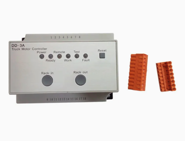
| Selection Factor | Key Requirement | Verification Method |
|---|---|---|
| Control voltage | Match auxiliary supply | Electrical specification check |
| Actuator interface | Match motor or mechanism | Mechanical compatibility review |
| Feedback contacts | Provide accurate position signals | Functional contact test |
| Interlocking | Support required switching logic | Sequence testing |
| Environment | Suit installation conditions | Protection rating review |
How Should Commissioning and Maintenance Be Performed?
Commissioning should verify electrical connections, mechanical movement, interlocking, and feedback signals. Technicians should first compare actual wiring with approved circuit diagrams. Next, they should test control voltage at the relevant terminals. Each operating command should then produce the expected actuator response. Position contacts require separate verification because mechanical movement does not guarantee correct electrical feedback. Interlocking tests should include both permitted and blocked operating conditions. Remote commands should also receive confirmation from the correct position signals. During maintenance, technicians should inspect terminals for looseness and signs of overheating. They should examine auxiliary contacts for wear and verify actuator movement for abnormal resistance. Test records should document measured conditions and detected faults. Consistent commissioning and maintenance practices provide a practical foundation for dependable switchgear operation.
How Does Remote Control Affect Operational Management?
Remote operation allows authorized personnel to issue commands without standing directly beside the switchgear. The control system must still verify permissive conditions before executing each command. Accurate feedback then confirms the resulting equipment state at the remote interface. Communication failure should never be treated as proof that the switch reached its requested position. Local indicators and independent verification remain important for critical switching procedures. Automation systems can also record command events, operating states, and fault conditions. These records support troubleshooting and help identify recurring operational problems. Remote control therefore depends on more than communication hardware. It requires reliable interlocking, accurate position feedback, stable control power, and correctly configured logic. When these elements work together, operators gain better visibility while reducing unnecessary field interaction.
Why Does Correct Configuration Matter?
Correct configuration determines whether the control system responds to commands safely and predictably. An incorrect terminal assignment can reverse feedback indications or prevent the actuator from operating. Wrong interlocking logic can also block legitimate commands or permit unsuitable sequences. Engineers should verify every input and output against approved documentation before commissioning. Mechanical travel should match the electrical position signals at each operating endpoint. Timing parameters may require adjustment when actuator characteristics differ between switchgear models. Technicians should record final settings so future maintenance teams can reproduce the approved configuration. Configuration reviews should also occur after major modifications to the switchgear control circuit. A disciplined approach reduces troubleshooting time and helps maintain consistent operation. Ultimately, reliable grounding control depends on accurate integration between mechanical equipment, electrical circuits, and operating logic.
FAQ
What is the main purpose of an electric earthing switch controller?
The primary purpose is to manage and verify controlled grounding operations within switchgear. It receives an operating command and checks required permissive conditions before activating the mechanism. Auxiliary contacts then provide feedback about the actual switch position. Interlocking logic can prevent unsuitable operations when another device has an incompatible state. The controller can also transmit status information to local indicators or remote monitoring systems. Its effectiveness depends on correct wiring, compatible control voltage, reliable actuator operation, and accurate feedback contacts. Regular functional testing helps confirm that every command produces the expected mechanical and electrical response. Proper integration therefore supports safer switching procedures and more reliable equipment management.
Why does an earthing switch need interlocking?
Interlocking prevents operations that could conflict with the intended electrical switching sequence. An earthing switch may interact with circuit breakers, disconnectors, and other devices in the same switchgear assembly. Without suitable interlocking, an incorrect command could create an unsafe equipment state. Electrical interlocking uses signals, auxiliary contacts, and relay logic to block prohibited commands. Mechanical interlocking can add a physical barrier against certain movements. Engineers often combine both methods because each provides a different layer of protection. Commissioning should test every interlock under both permitted and prohibited conditions. Technicians should also verify feedback contacts because faulty signals can affect the interlocking decision. Properly maintained interlocking contributes significantly to predictab