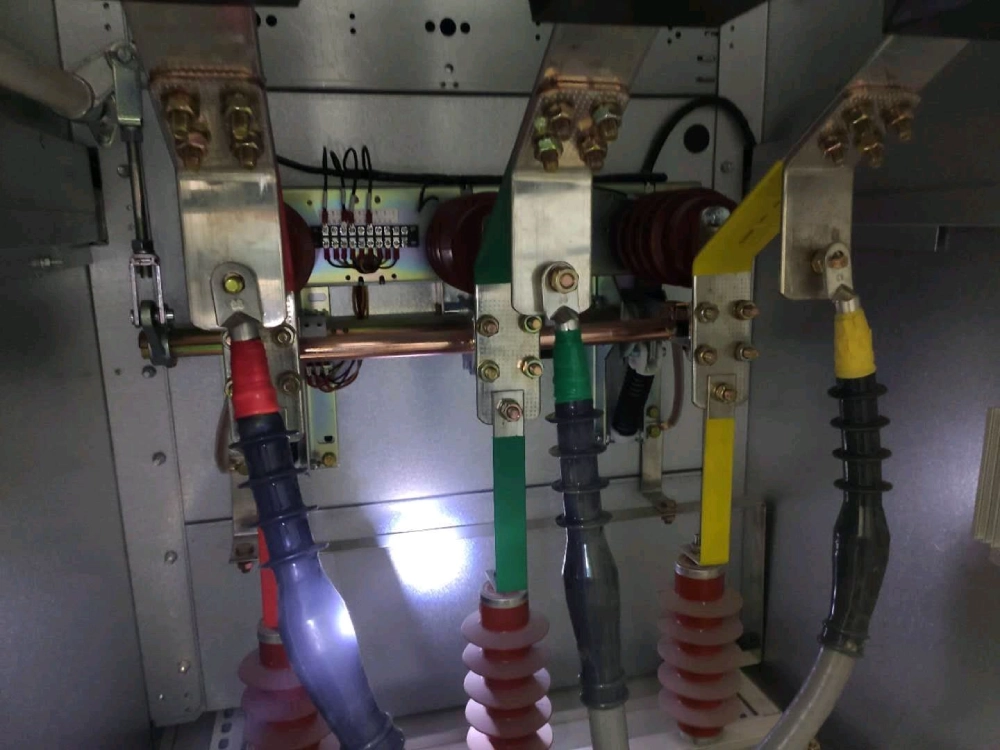

What Features Matter In A Control Module For Earthing Switch?
Control module for earthing switch features interlocking, position feedback, safety, communication, selection, wiring, and maintenance.
Control Module For Earthing Switch: Core Functional Requirements
A control module for earthing switch coordinates switching commands, safety conditions, and position feedback. It connects the operating mechanism with the wider switchgear control circuit. Reliable logic prevents commands when electrical or mechanical conditions remain unsafe. The module also reports switch status to local indicators or supervisory systems. Engineers should therefore assess more than nominal voltage and enclosure size. Interlocking logic, contact configuration, response time, and signal isolation can affect operating safety. Environmental resistance also matters in substations and industrial distribution rooms. A suitable design should match the earthing switch mechanism and the control scheme. Clear terminal identification simplifies commissioning and later maintenance. These factors create a practical basis for comparing control modules across different switchgear configurations.
Interlocking Logic For Safe Earthing Operations
Interlocking represents one of the most important safety functions within switchgear control systems. It establishes conditions that must exist before an operating command becomes valid. For example, the system can block earthing operations while the connected circuit remains energized. Mechanical interlocks can provide physical restrictions, while electrical interlocks manage control signals. Combining both approaches creates multiple barriers against incorrect operation. Engineers should examine how auxiliary contacts communicate the position of associated equipment. The logic should also distinguish between confirmed open, closed, and intermediate states. Poorly designed interlocking can create misleading indications or prevent necessary operations. Proper coordination requires accurate electrical diagrams and clearly defined operating sequences. Testing should reproduce normal and abnormal conditions before equipment enters service.
Position Monitoring And Status Feedback
Position monitoring confirms whether the earthing switch has reached its intended mechanical position. Auxiliary contacts commonly provide electrical feedback from the operating mechanism. Limit switches can also indicate travel completion during motorized or electrically assisted operation. A reliable feedback circuit should distinguish open and closed states without ambiguity. Intermediate positions deserve attention because incomplete travel can create operational risks. Contact bounce may produce unstable signals during mechanical movement. Signal conditioning can reduce unwanted transitions within sensitive control circuits. Engineers should also consider contact ratings, insulation levels, and expected switching frequency. Local indicators should correspond with actual mechanical positions rather than command status alone. Remote systems should receive confirmed feedback whenever the application requires supervisory monitoring. Accurate position information supports safer switching decisions and faster fault diagnosis.
Electrical Control And Signal Interface Design
The electrical interface determines how the module communicates with external switchgear components. Typical circuits include control power, command inputs, position outputs, alarm contacts, and permissive signals. Voltage compatibility must match the available control supply without relying on assumptions. Common systems may use direct current supplies for reliable control circuit operation. Terminal arrangements should provide clear separation between power circuits and low-level signals. Galvanic isolation can reduce interference between electrically different circuits. Contact capacity also requires careful checking against connected loads and switching characteristics. A relay output suitable for signaling may not support a larger inductive load. Surge suppression can protect contacts from voltage spikes caused by coils and contactors. Proper interface planning reduces wiring errors during installation. It also improves troubleshooting because each signal has a defined electrical purpose.
Control Module For Earthing Switch: Protection And Safety Features
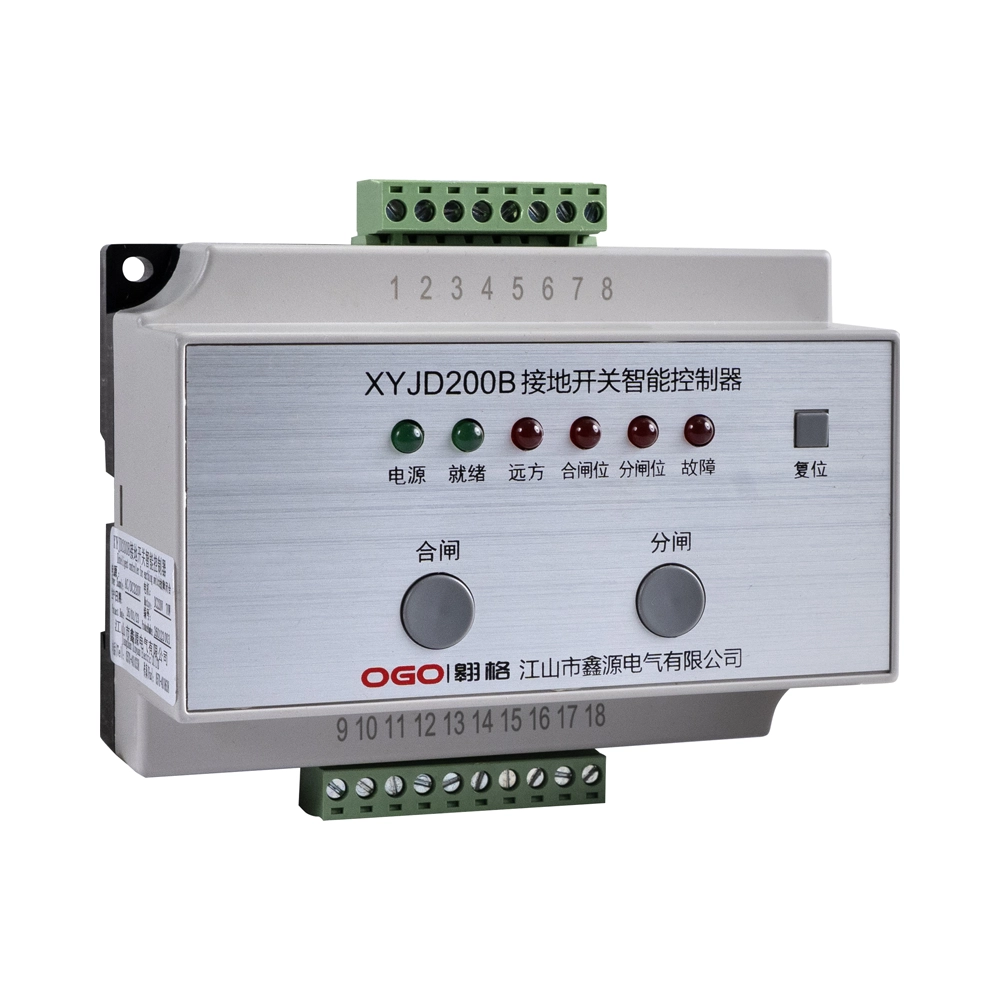
A robust control module for earthing switch should respond predictably when abnormal conditions occur. Undervoltage can prevent reliable actuator operation and create incomplete switching sequences. Overcurrent protection can protect control wiring and connected components from excessive electrical stress. Timing supervision can identify operations that exceed the expected travel period. Alarm outputs should distinguish command failures from position feedback problems. Some systems also use permissive circuits to prevent commands under predefined unsafe conditions. These functions should operate independently where the application requires higher protection integrity. A controller should never rely only on software logic when physical interlocking provides stronger protection. XYJD200B Smart Controller for Grounding Switch can represent a practical reference when evaluating integrated control functionality. Engineers should still verify every specification against the actual switchgear design. Protection features become valuable only when they align with real operating conditions.
Response Time, Reliability, And Environmental Performance
Response time affects how quickly a control system reacts to a valid switching command. Excessive delay can complicate coordinated switching sequences and remote operating procedures. However, fast response alone does not guarantee reliable performance. The control circuit must also reject unstable or conflicting input signals. Relay endurance, terminal quality, and component temperature ratings influence long-term reliability. Humidity can cause corrosion, insulation deterioration, and leakage across contaminated surfaces. Temperature changes may also affect electronic components and mechanical contact performance. Industrial installations can expose modules to vibration and electromagnetic interference. Appropriate enclosure protection helps limit the impact of dust and moisture. Engineers should review operating temperature, storage temperature, humidity limits, and vibration resistance. These environmental specifications should reflect the actual installation site. Reliable operation depends on matching the module design with its surrounding conditions.
Communication Functions For Intelligent Switchgear
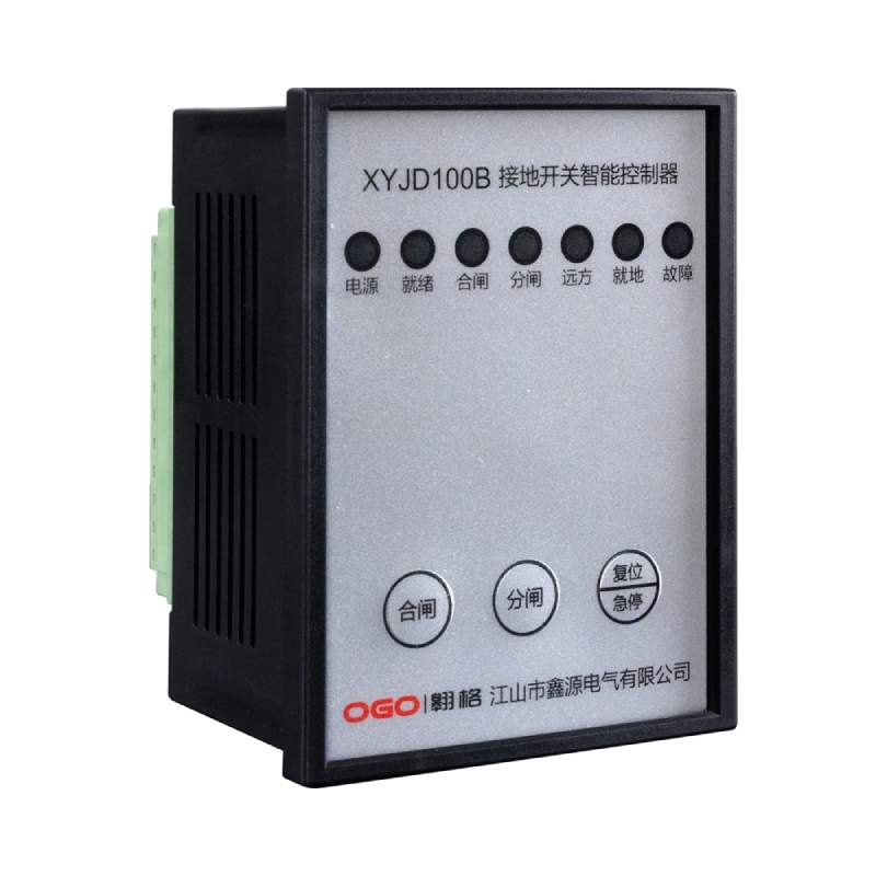
Modern substations increasingly connect switchgear control devices with supervisory platforms. Communication functions can provide remote status, alarms, event information, and operating records. Digital communication reduces the need for extensive point-to-point wiring in larger installations. However, communication capability should complement essential hardwired safety circuits. Critical interlocking functions should remain available through dependable local control paths. Protocol compatibility must also match the supervisory system used at the installation. Engineers should verify communication interfaces, addressing methods, data points, and diagnostic functions. Signal mapping requires particular attention during system integration. Incorrect mapping can display an apparently valid status for the wrong device. Controller for Grounding Switch applications may therefore require both local and remote interface planning. A well-designed communication structure improves visibility without weakening fundamental electrical safety.
Key Specifications To Compare Before Selection
Selection should begin with the actual electrical and mechanical requirements of the switchgear. Nominal control voltage represents only one part of the specification. Engineers should compare input quantities, output contacts, contact ratings, and feedback arrangements. Installation dimensions can become critical when retrofit space remains limited. Terminal direction and wiring access can also affect installation efficiency. Environmental ratings should correspond with the cabinet location and operating conditions. Communication requirements become important when the module connects to automation systems. A control module for earthing switch should match the operating mechanism, circuit design, and required safety functions. The table below provides a practical comparison framework for technical evaluation.
| Specification | Why It Matters | Verification Point |
|---|---|---|
| Control Voltage | Ensures reliable command operation | Match the available control supply |
| Input Signals | Supports commands and permissive logic | Confirm quantity and electrical type |
| Output Contacts | Provides status and alarm signals | Check rating and contact arrangement |
| Position Feedback | Confirms mechanical switch status | Verify open and closed indications |
| Communication | Supports remote supervision | Check interface and protocol compatibility |
| Environmental Rating | Protects operation under site conditions | Compare temperature and humidity limits |
Installation And Wiring Considerations
Installation quality directly affects the performance of a control system. Technicians should follow the approved schematic and terminal assignment during every connection. Control power should remain isolated while wiring work takes place. Each conductor should receive clear identification before commissioning begins. Terminal tightening requires appropriate attention because loose connections can create heat and intermittent signals. Signal cables should remain separated from high-power conductors when practical. Such separation can reduce electromagnetic interference within sensitive control circuits. The module should also remain accessible for inspection and future testing. Before energization, technicians should verify polarity, continuity, insulation condition, and terminal allocation. Functional checks should then confirm every command and feedback path. These steps help identify wiring errors before they affect operational equipment. Installation discipline therefore contributes directly to system reliability and maintenance efficiency.
Practical Checklist For Control Module Evaluation
A structured checklist helps engineers compare technical requirements without overlooking smaller interface details. The following points provide a practical screening method for procurement and commissioning:
- Confirm the rated control voltage and allowable voltage tolerance.
- Verify input and output quantities against the electrical schematic.
- Check interlocking conditions for every operating sequence.
- Confirm open, closed, and intermediate position feedback.
- Review contact ratings for connected relays and signaling circuits.
- Verify communication interfaces and required data points.
- Compare environmental temperature, humidity, and vibration limits.
- Check mounting dimensions and terminal accessibility.
- Confirm alarm functions and abnormal-operation indications.
- Review testing requirements before final commissioning.
Each point should connect directly with the equipment specification and operating philosophy. Procurement teams should avoid selecting modules through voltage matching alone. A technically compatible unit may still lack required feedback or communication functions. Installation constraints can also eliminate otherwise suitable products. Early verification reduces redesign work and prevents commissioning delays. The checklist becomes especially useful when several control architectures appear similar. Engineers can assign acceptance criteria before comparing suppliers or technical proposals. This approach creates a consistent basis for technical evaluation. It also makes later maintenance documentation easier to organize. Clear criteria support better decisions when project requirements change during engineering.
Maintenance And Troubleshooting Priorities
Routine maintenance should focus on control power, terminals, contacts, feedback devices, and communication paths. A control module for earthing switch requires regular inspection to maintain dependable switching performance. Loose terminals can cause intermittent operation that resembles an electronic control failure. Contact oxidation may increase resistance and weaken low-level feedback signals. Mechanical travel should also receive attention because poor movement can affect position confirmation. Technicians should compare actual switch position with local and remote indications. Differences between these signals can reveal feedback wiring or auxiliary contact problems. Control voltage measurements should occur under both standby and operating conditions. Voltage drops may indicate overloaded circuits, poor connections, or aging components. Alarm history can provide additional evidence when intermittent problems occur. Maintenance records should document measured values rather than only recording pass or fail results. Trend information helps identify deterioration before a complete control failure develops.
Performance Verification Before Commissioning
Commissioning should verify every control sequence against the approved electrical and functional design. Technicians should first confirm correct control power and signal polarity. Individual inputs should then receive controlled test signals. Output contacts should respond according to their assigned functions. Position feedback requires mechanical movement tests rather than electrical simulation alone. Interlocking tests should reproduce both permitted and prohibited operating conditions. Alarm tests should verify that abnormal states reach the intended local or remote interface. Communication tests should confirm correct device identity and status mapping. Technicians should record test results for every critical function. Any unexpected response should trigger investigation before normal operation begins. Final acceptance should confirm that physical position, electrical status, and displayed status agree. A disciplined commissioning process reduces the risk of hidden logic or wiring problems.
Frequently Asked Questions
What does an earthing switch control module do?
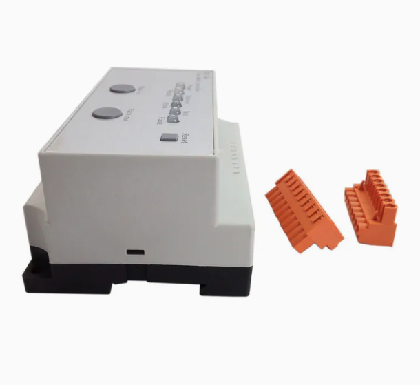
A control module coordinates commands, safety conditions, position signals, and external control interfaces. It can prevent invalid operations through electrical interlocking logic. The module may also transmit switch status to local indicators or supervisory systems. Its input and output circuits connect operating commands with auxiliary contacts and other control devices. Depending on the design, additional functions can include alarms, timing supervision, communication, and fault indication. Selection should consider the switch mechanism, control voltage, signal requirements, and installation environment. A suitable module should support the complete operating sequence rather than one isolated function. Proper testing remains essential because correct module operation depends on wiring, interlocking, and mechanical movement working together.
Why is interlocking important for grounding switch operation?
Interlocking prevents an unsafe operating sequence from receiving a valid command. For example, a grounding operation may require confirmation that another switching device remains open. Electrical interlocks transmit these conditions through contacts, relays, or control logic. Mechanical interlocks can add physical restrictions that do not depend on electronic processing. Using both methods creates stronger protection against human error and control faults. Position feedback also strengthens interlocking because the system can verify actual equipment status. Engineers should define every permissive condition within the approved control philosophy. Testing should include normal commands, blocked commands, conflicting signals, and incomplete travel. Effective interlocking therefore protects personnel, equipment, and the wider power distribution system.
Which specifications should engineers check before selection?
Engineers should first verify control voltage, input quantities, output contacts, and position feedback requirements. Interlocking logic should match the operating sequence of the complete switchgear assembly. Contact ratings must suit connected loads, especially when coils or inductive devices operate through relay contacts. Environmental ratings should match the installation temperature, humidity, vibration, and enclosure conditions. Communication interfaces require additional checks when remote monitoring or automation forms part of the system. Mounting dimensions and terminal accessibility also matter during retrofit projects. Documentation should clearly identify terminals, signals, operating conditions, and testing procedures. Comparing these factors together provides a stronger technical basis than selecting a module from voltage or appearance alone.