
How Does an MV Switchgear Fault Indicator Locate Faults?
Select an MV switchgear fault indicator for your network. Check fault thresholds, response time, earthing, reset settings, and alarms.
How It Helps Narrow the Faulted Section
An MV switchgear fault indicator records when its sensors detect fault conditions that meet the configured criteria. Operators compare indications at successive points with the network's actual switching arrangement. On a simple radial feeder, indications can identify the path carrying qualifying fault current toward the fault. A change between a responding point and a downstream clear point can help narrow the search. Confirm sensor health, settings, and event timing before interpreting that boundary. Use the result alongside protection records and the operating diagram. This supports investigation and the authorized restoration process.
What an MV Switchgear Fault Indicator Measures
Phase sensors detect the current behavior associated with short circuits according to the device's algorithm and settings. An earth-fault channel monitors the specified residual or earth-current signal. Each function needs suitable sensors and a detection method that fits the network. Record the neutral earthing arrangement and the expected fault currents during selection. A device's voltage application range provides only one part of that review. Check its pickup threshold, response time, reset behavior, and available outputs. Include the protection clearing time so engineering can confirm whether the indicator can capture the relevant event.
When Can the Indication Boundary Be Misleading?
A radial interpretation assumes a known source direction and a current path that matches the operating diagram. Closed rings or distributed sources can feed a fault from more than one direction. Capacitive earth-current contributions can also complicate interpretation on isolated or compensated networks. Those conditions call for assessment of the detection principle and any required directional function. Record the switch positions and source connections at the event time. Compare available direction information with the protection record before assigning a faulted section. A missing indication also requires checks of pickup, event duration, and sensor condition.
How Do You Set an MV Switchgear Fault Indicator?
Choose settings from the network study and the indicator's documented detection criteria. The pickup should detect the target fault while accounting for normal load and relevant transient conditions. Compare the minimum expected fault current with the proposed threshold. Then check the time criterion against the protection device's clearing behavior. A fault below pickup can remain unrecorded. Likewise, an event shorter than the required detection time may escape indication. Include the sensor and device tolerances in the assessment. Ask the supplier to confirm response characteristics and any inrush restraint for the exact variant.
What Does the EKL4 Technical Sheet Specify?
The EKL4 cable-fault product sheet publishes the settings summarized below. Its factory defaults provide a starting configuration that requires project review. For example, a 100 A target earth fault exceeds a 10 A pickup in magnitude. Engineering must also check duration, sensor installation, and network suitability before expecting a valid indication. The sheet lists application to systems up to 20 kV. Confirm the supplied sensor assembly and insulation requirements against the cabinet design. Keep the accepted settings with the model code and commissioning record.
How EKL4 settings affect fault-section identification
| Parameter | Published information | Effect on fault location |
|---|---|---|
| Short-circuit pickup | Adjustable from ≥150 A, factory setting 630 A | A pickup above the fault current can leave part of the fault path unmarked. |
| Earth-fault pickup | 5–400 A, factory setting 10 A | A threshold above the target earth-fault current can hide passage through a monitored section. |
| Detection delay | 20–300 ms, default 60 ms for short circuits and 200 ms for earth faults | If protection clears the fault before detection completes, an unrecorded passage can suggest a misleading boundary. |
| Automatic reset | 1 second–32 hours, factory setting 8 hours | Early reset can erase upstream indications before inspection, obscuring the fault-current path. |
| Protection rating | Main unit IP40, sensors IP65 | Unsuitable exposure can impair a sensor or display, making a clear indication unreliable as location evidence. |
Which Alarm and Communication Functions Do You Need?
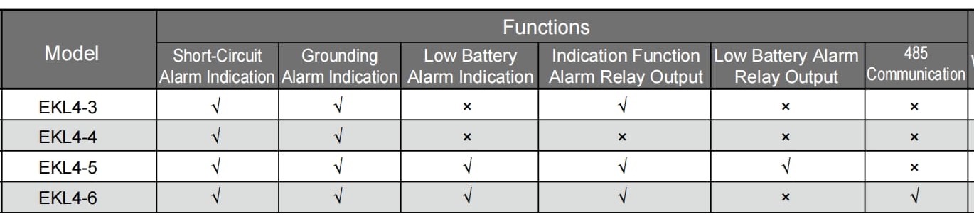
The EKL4 selection table distinguishes four versions with different reporting functions. EKL4-4 provides short-circuit and earth-fault indication. EKL4-3 adds an indication alarm relay output. EKL4-5 includes low-battery indication and a low-battery alarm relay output. EKL4-6 includes low-battery indication and RS485 communication alongside its alarm relay. Confirm protocol details and the point mapping before connecting a communicating version to the monitoring system. The integrated voltage-presence and grounding-fault indicator offers another product configuration to review. Request its exact detection, indication, and output specifications when those functions form part of the project.
How Should You Preserve and Test the Evidence?
Record local indications, event time, switch positions, and available remote alarms before resetting the device. Compare the automatic reset interval with the likely inspection or remote response time. A short retention period can erase evidence before the team arrives. During commissioning, use the approved method to verify each phase channel, the earth-fault channel, and fitted outputs. Confirm reset operation and battery supervision where the version provides them. The test record should identify sensors, settings, and expected responses. Retain the observed results with the cabinet's maintenance documentation for future fault investigation.
Frequently Asked Questions
Can the indicator disconnect the faulted circuit?
The published EKL4 functions cover indication, alarm outputs, and communication according to the selected version. Fault interruption belongs to the cabinet's approved protection and switching arrangement. If a design uses an indicator output in a wider automation scheme, engineering must verify that complete function. Check output ratings, operating logic, and the required protection performance before accepting such a design. For normal fault investigation, combine indications with the protection event record and network diagram. Follow the authorized switching procedure when isolating a section and restoring the healthy network.
Why might a known fault leave no indication?
The fault current may fall below pickup or persist for less than the required detection time. Sensor problems, incorrect settings, or reset timing can also affect the evidence available afterward. Start with the protection record and compare current and duration with the accepted configuration. Check the sensor installation, device condition, and whether anyone reset the display. For earth faults, revisit the network earthing arrangement and the suitability of the detection principle. Qualified staff should follow the manufacturer's diagnostic procedure and record findings before changing settings or replacing components.
What should I provide when requesting a quotation?
Provide the system voltage, network earthing method, feeder arrangement, and required fault-detection functions. Include expected fault currents, protection clearing times, cable dimensions, and sensor mounting constraints. Specify whether the project needs local indication, relay alarms, battery supervision, or communication. Add the desired evidence retention and reset arrangements. Ask for the exact model, detection method, setting ranges, and matching sensor documents with the quotation. For a retrofit, include the original configuration and cabinet drawings. Those records help the supplier and project engineer review the same operating requirements.