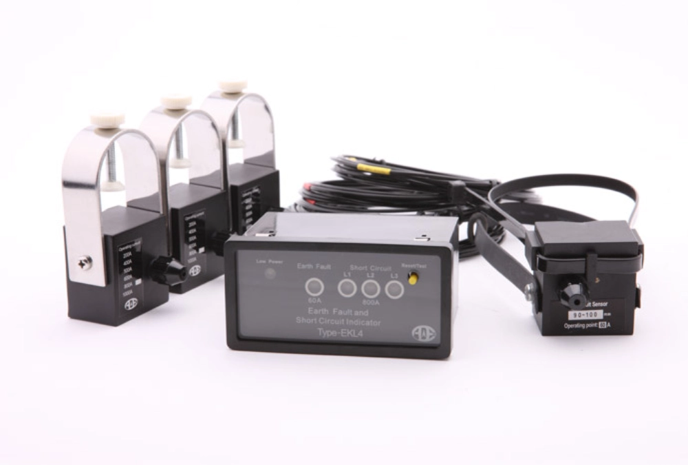

How Does A Short Circuit Fault Indicator Work?
Choose the right earth fault indicator alarm threshold based on grounding systems, fault current, sensor sensitivity, and testing needs.
A short circuit fault indicator helps maintenance teams identify faulted sections in medium-voltage distribution networks. Short circuits can interrupt power supplies, damage electrical equipment, and require extensive fault investigation. Without reliable fault information, technicians may spend considerable time inspecting cables and distribution equipment. Fault indicators detect abnormal current conditions and provide visible or electrical alarm signals. These signals help operators narrow down fault locations and reduce unnecessary inspections. Their applications include underground cable networks, ring main units (RMUs), switchgear, and overhead distribution lines.
What Is a Short Circuit Fault Indicator?
A short circuit fault indicator is an electrical monitoring device that detects abnormal overcurrent associated with short-circuit faults. It typically uses a current sensor installed around a conductor to monitor electrical conditions. When the measured current meets the configured fault criteria, the indicator activates a local display or alarm output. The indication may remain active after protective equipment disconnects the faulted circuit. This allows maintenance personnel to identify affected sections even after fault current disappears. Unlike circuit breakers, fault indicators do not interrupt fault current. Their primary purpose is to support fault identification and location. Depending on the configuration, some devices also detect earth faults and provide remote monitoring signals.
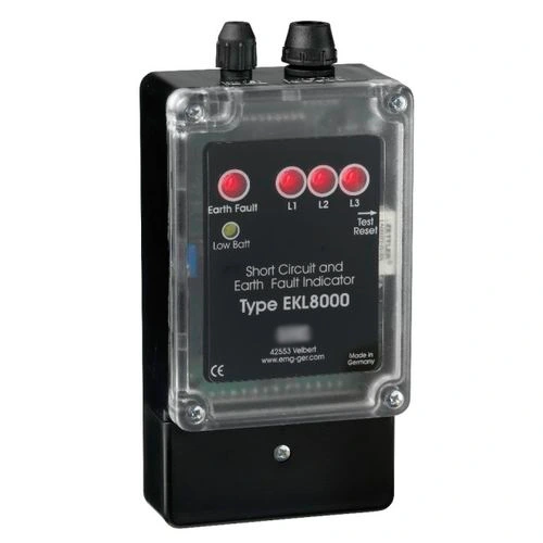
How Does a Short Circuit Fault Indicator Work?
A short circuit fault indicator operates by monitoring conductor current through a magnetic sensing element, such as a current transformer. During normal operation, the measured current remains within the expected operating range. When a short circuit occurs, current may increase rapidly beyond the configured pickup threshold. The detection circuit evaluates the current magnitude and duration before activating a fault indication. Some devices also consider voltage loss or other conditions to improve detection reliability. Once triggered, the indicator may illuminate an LED, activate a mechanical display, or operate an alarm relay. The fault indication remains available according to the configured reset logic, helping technicians investigate the affected circuit.
What Are the Main Types of Fault Indicators?
Fault indicators are available in several configurations for different distribution applications. Cable-mounted devices monitor current in underground cables, while overhead-line indicators attach to distribution conductors. Panel-mounted displays provide visible fault information on switchgear or RMU panels. Some products detect short circuits only, while others combine short-circuit and earth-fault detection. Integrated devices can reduce the need for separate monitoring components in suitable installations. The selection depends on conductor arrangement, installation space, fault detection requirements, and indication methods. Available short-circuit and earth-fault indicators include configurations suitable for cable distribution equipment.
The following table compares common configurations.
| Indicator Type | Main Function | Typical Application |
|---|---|---|
| Cable-Mounted | Detects abnormal cable current | Underground cable networks |
| Overhead-Line | Detects faults on overhead conductors | Distribution feeders |
| Panel-Mounted | Displays detected fault status | RMUs and switchgear |
| Combined Fault Indicator | Detects short circuits and earth faults | Medium-voltage cable systems |
How Do Fault Indicators Locate Short Circuits?
Fault indicators help locate short circuits by showing which sections of a distribution network experienced fault current. Consider a radial feeder with several indicators installed along its length. When a downstream short circuit occurs, upstream indicators along the fault-current path may activate. Indicators beyond the fault location generally remain inactive when no fault current passes through them. Maintenance teams compare these indications to narrow the suspected fault section. For example, if two consecutive upstream indicators activate but the next downstream indicator remains inactive, the fault may lie between them. This method reduces the area requiring inspection. However, branched networks, multiple power sources, and automatic switching require additional analysis of the network configuration.
Why Are Fault Indicators Important in Distribution?
Fault indicators improve distribution maintenance by providing information about abnormal current events. Without sectional fault indication, technicians may need to inspect extensive cable routes or multiple distribution cabinets. Local alarms help identify areas requiring attention, reducing unnecessary inspection work. In underground cable systems, this information is particularly useful because faults are not directly visible. When appropriate communication interfaces are available, alarm contacts can also connect to remote monitoring equipment. Operators may receive fault status through an RTU, PLC, or compatible monitoring system. Repeated indications can support maintenance planning by identifying frequently affected feeder sections. These benefits depend on proper installation, reliable detection settings, and suitable network coordination.
What Specifications Matter When Selecting One?
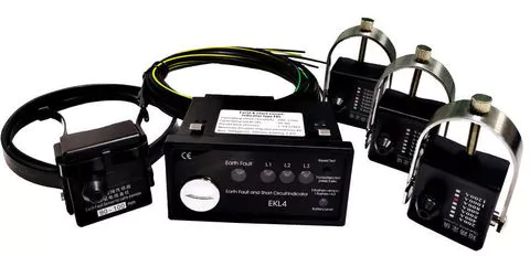
Selecting a short circuit fault indicator requires evaluating the distribution network and its expected fault conditions. The pickup threshold should exceed normal operating current and anticipated non-fault transients while remaining sensitive to relevant short circuits. Detection delay and reset settings must also suit the protection scheme. Engineers should verify sensor dimensions, conductor compatibility, operating temperature, power supply, and fault-current withstand ratings. For example, the EKL4 Short-Circuit Grounding Fault Indicator for Cables provides adjustable fault settings, automatic reset, and alarm relay output. Its listed short-circuit sensor withstand rating is 20 kA for four seconds. Actual settings and product compatibility should be confirmed against the installation requirements.
| Specification | Selection Consideration |
|---|---|
| Pickup Current | Expected load and minimum fault current |
| Detection Delay | Protection coordination and transient behavior |
| Current Withstand | Maximum prospective short-circuit current and duration |
| Reset Method | Automatic, timed, or manual reset requirements |
| Power Supply | Battery, current-powered, or auxiliary supply |
| Alarm Output | Local indication or remote relay monitoring |
| Sensor Dimensions | Cable diameter and available installation space |
What Causes False Fault Indications?
False fault indications may occur when abnormal current conditions resemble genuine short circuits. Transformer energization can produce temporary inrush currents significantly higher than normal operating current. Capacitor-bank switching and other electrical transients may also affect sensitive detection circuits. If the pickup threshold is too low, these temporary events can activate the indicator. Incorrect sensor installation, unsuitable detection delays, or configuration errors may introduce additional problems. In networks with distributed generation, changing fault-current direction can complicate interpretation. Engineers can reduce unwanted indications by coordinating detection thresholds with normal load characteristics and protection settings. Suitable transient discrimination and correct sensor installation further improve detection reliability.
How Are Fault Indicators Installed and Tested?
Proper installation is essential for reliable fault indication. Cable-mounted current sensors should be positioned according to the manufacturer's instructions and the intended measurement arrangement. In three-phase cable systems, each phase sensor must correspond to the correct conductor. Panel-mounted displays should remain visible and accessible during permitted inspection activities. Where remote monitoring is required, technicians should verify alarm relay contacts and their connections to external equipment. Before commissioning, the installation should undergo functional checks using an approved test procedure. These checks may include sensor operation, fault indication, relay output, and reset behavior. Testing must follow electrical safety procedures, particularly when working around energized medium-voltage equipment.
How Do Fault Indicators Differ from Protection Relays?
Fault indicators and protection relays perform different functions within electrical distribution systems. A protection relay monitors electrical conditions and can initiate circuit-breaker operation when its protection criteria are satisfied. Its primary function is to protect equipment and limit the consequences of electrical faults. A fault indicator mainly records or displays that qualifying fault conditions occurred at its monitoring location. It helps maintenance personnel identify affected sections after protective equipment operates. Fault indicators generally do not provide the comprehensive protection functions required for circuit interruption. Both devices can work together within a coordinated distribution system. Protection relays initiate protective actions, while fault indicators provide additional information for fault location and maintenance.
FAQ
Can a Short Circuit Fault Indicator Detect Ground Faults?
Some short-circuit fault indicators can detect ground faults, but this capability depends on the device design. Basic short-circuit indicators primarily monitor excessive phase current associated with short-circuit conditions. Combined devices incorporate additional detection functions for earth faults. These may use residual-current measurement, zero-sequence current sensors, or other methods suited to the network. Earth-fault detection requirements depend on the grounding arrangement and expected fault-current magnitude. For example, low-current ground faults may require more sensitive detection than conventional phase overcurrent monitoring provides. Engineers should confirm the supported fault types and detection ranges before selecting a combined device for medium-voltage distribution applications.
Does a Fault Indicator Need an External Power Supply?
Not every fault indicator requires an external power supply. Some devices use internal batteries to operate their monitoring circuits and maintain fault indications. Other designs obtain operating energy from the magnetic field surrounding an energized conductor. Certain panel-mounted or communication-enabled devices may require an auxiliary AC or DC supply. The appropriate power arrangement depends on the application and monitoring functions. Battery-powered models require consideration of service life and replacement intervals. Current-powered designs may have minimum operating-current requirements. When remote monitoring is necessary, engineers should also verify the power requirements of communication equipment and connected alarm interfaces.
How Does a Fault Indicator Reset After a Short Circuit?
Fault indicators use different reset methods depending on their design and configuration. Automatic reset systems may clear the indication after normal electrical conditions return and the programmed requirements are satisfied. Timed reset functions clear the indication after a predetermined interval, even when normal load current has not returned. Manual reset requires maintenance personnel to operate a dedicated control or approved reset mechanism. Some advanced devices also support remote reset commands through