
How Does Earth Fault Indicator Relay Output Work?
Earth fault indicator relay output, covering wiring, testing, output types, and selection for reliable fault monitoring.
Earth fault indicator relay output helps distribution teams transmit fault signals to external monitoring and alarm systems. It supports faster fault localization and improves visibility across medium-voltage distribution networks. However, its actual functions depend on the indicator model and output configuration.
Knowing how relay output works helps engineers select compatible equipment, plan wiring, and verify alarm responses. It also helps switchgear manufacturers integrate fault indicators into existing monitoring systems. The following sections explain the operating principle, output types, connection requirements, testing procedures, and common troubleshooting issues.
What Is Earth Fault Indicator Relay Output?
An earth fault indicator detects abnormal grounding current and indicates a potential fault in an electrical distribution network. Some models also provide relay contacts for external alarm or monitoring circuits. These contacts allow the device to communicate a fault status beyond its local display.
The relay output acts as an electrical interface between the indicator and external equipment. Depending on the design, it can activate an alarm, provide a status signal, or interface with a suitable control circuit. The output does not necessarily interrupt the primary electrical circuit.
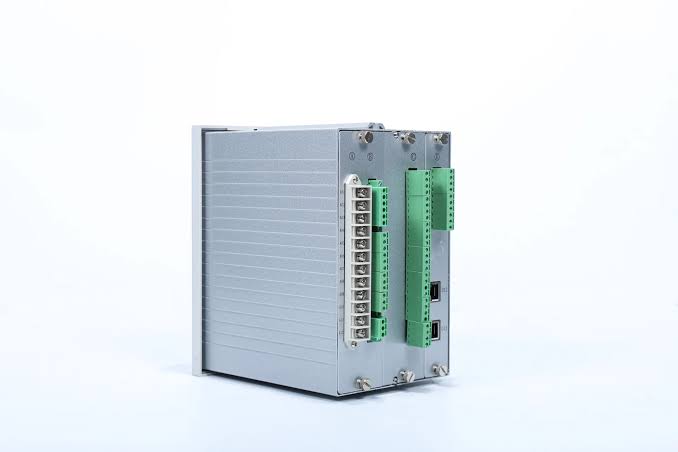

When evaluating earth fault indicator relay output, engineers should distinguish three functions:
- Local indication: LEDs or displays show fault status at the installation point.
- Relay output: Electrical contacts communicate status to an external circuit.
- Communication output: Supported interfaces transmit data to compatible monitoring systems.
These functions may coexist, but they are not interchangeable. A device with relay contacts does not automatically support digital communication or direct circuit breaker tripping.
How Does the Relay Output Work?
The operating sequence starts when the indicator monitors current through its designated sensor. Depending on the system design, the sensor detects grounding current or other abnormal current conditions. The device compares the measured signal with its configured detection criteria.
When the criteria are satisfied, the indicator processes the event and activates its configured alarm response. If relay output is supported, the internal switching mechanism changes the contact state. The connected equipment then receives a signal indicating the detected condition.
The external system interprets this signal according to its own control logic. For example, a monitoring input may display an alarm or notify maintenance personnel. A properly engineered protection circuit may also use a suitable output to initiate a protective action.
The exact response depends on the device's detection logic, relay configuration, and reset settings. Some indicators provide automatic reset, while others use manual or external reset methods. Engineers should confirm these behaviors before integrating the indicator into a distribution system.
What Types of Relay Outputs Are Used in Earth Fault Indicators?
Relay output configurations vary by product design and application requirements. Engineers should confirm the available functions before specifying an indicator.
Alarm output sends a signal when the device detects a configured fault condition. The signal can activate an external alarm or notify a monitoring system. This function helps maintenance teams respond without relying solely on local visual indications.
Trip output can initiate a circuit breaker trip through a suitable protection circuit. However, the indicator must support this function, and the complete circuit must meet the project's protection requirements. An ordinary alarm contact should not be assumed suitable for direct tripping.
Dry contact output provides electrically isolated switching contacts without supplying power to the external circuit. The receiving circuit requires a compatible power source and suitable electrical ratings.
Remote monitoring output allows fault status to reach control equipment. Depending on the product, this may use relay contacts or a separate communication interface. For example, Xinyuan's EKL4-W Current Temperature Fault Online Monitor supports RS485 communication using the MODBUS protocol. This is a communication function rather than simply a relay contact.
How Is Relay Output Connected to External Equipment?
Correct wiring ensures that a fault signal reaches the intended receiving device. The connection must follow the manufacturer's wiring diagram and the external circuit's electrical requirements.
Common relay terminals include the following:
- COM (Common): The shared terminal for the switching contacts.
- NO (Normally Open): The contact is open in its defined normal state and closes when the relay changes state.
- NC (Normally Closed): The contact is closed in its defined normal state and opens when the relay changes state.
These descriptions assume a conventional changeover relay. The actual normal state depends on the manufacturer's defined operating condition, which may include power loss or a fault event.
A typical integration connects the relay contacts to a compatible PLC digital input, RTU input, or external alarm circuit. Engineers must check the input voltage, contact rating, isolation requirements, and expected signal logic. They should also determine whether the receiving system interprets contact closure or contact opening as an alarm.
Before commissioning, verify terminal assignments against the actual product documentation. Never assume that two indicators use identical terminal layouts. Correct wiring also helps ensure that earth fault indicator relay output reaches the monitoring system without unwanted signal interruptions.
What Should You Check When Selecting Relay Output?
The right output configuration depends on the distribution network, monitoring architecture, and required fault response. Procurement teams should evaluate the following parameters before placing an order.
| Selection factor | What to verify |
|---|---|
| Output function | Alarm, status indication, or supported trip control |
| Contact configuration | NO, NC, COM, or changeover contacts |
| Contact rating | Permitted switching voltage and current |
| Power supply | Internal battery or external auxiliary supply |
| Reset behavior | Automatic, manual, or external reset |
| Integration | Compatibility with PLC, RTU, or monitoring inputs |
| Installation | Available space, terminals, and wiring access |
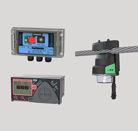
Contact ratings deserve particular attention. A relay's maximum switching voltage and current must suit the connected load. Inductive loads may require additional suppression or an intermediate relay.
Reset behavior also affects alarm handling. Automatic reset may clear an indication after the configured conditions are satisfied. A latching arrangement may retain the alarm until a reset command is received.
Engineers should confirm whether the output indicates a current fault, a recorded event, or the device's operating status. These signals have different meanings in a control system. Selecting the correct earth fault indicator relay output therefore requires checking both the device specifications and the receiving equipment's requirements.
How to Test the Relay Output?
Testing verifies that the indicator detects the intended condition and communicates the result correctly. It should form part of commissioning and routine maintenance.
- Inspect the wiring. Compare terminal connections with the approved diagram. Check conductor security and the receiving circuit's configuration.
- Verify the settings. Confirm the grounding-current threshold and other relevant detection parameters. Ensure they match the project's protection requirements.
- Simulate the required condition. Use the manufacturer's approved test procedure or a suitable test instrument. Do not create an uncontrolled ground fault on an energized network.
- Check the relay response. Observe whether the contacts change state as specified. Confirm the response against the product's operating logic.
- Verify the external signal. Check whether the PLC, RTU, alarm panel, or monitoring interface receives the expected status.
- Confirm the reset behavior. Determine whether the indication clears automatically or requires manual intervention. Record the results for future maintenance.
Testing should distinguish the indicator's internal response from the complete alarm chain. A relay may operate correctly while an external input remains incorrectly configured. Conversely, a monitoring system may appear functional even when the indicator fails to detect the intended condition.
Follow the manufacturer's safety procedures and isolate circuits where required. Testing must not cause unintended breaker operation or interrupt essential power supplies. These checks help confirm that earth fault indicator relay output performs as intended throughout the complete signal path.
What Are Common Relay Output Problems?
Relay output problems can originate inside the indicator, within the wiring, or in the receiving equipment. A systematic check helps narrow down the cause.
| Symptom | Possible cause | Recommended check |
|---|---|---|
| No output during a fault | Incorrect threshold or output configuration | Verify settings and approved test response |
| Local indication works, but remote alarm fails | Wiring or input logic mismatch | Check terminals and receiving input |
| Alarm remains active after a fault | Latching behavior or reset conditions | Confirm the reset procedure |
| Output changes unexpectedly | Incorrect settings or unstable fault conditions | Review detection logic and event records |
| Relay cannot operate the connected load | Incompatible contact rating | Check load requirements and use a suitable interface if needed |
An important distinction is whether the fault occurs during detection or signal transmission. If local indication works, the sensor and detection process may be operating correctly. However, this does not prove that the relay contacts or external wiring are functional.
If the output fails during an approved test, inspect the configuration and consult the manufacturer's documentation. Do not replace the indicator until the external circuit has also been checked.
FAQ About Earth Fault Indicator Relay Output
Can an Earth Fault Indicator Relay Output Trip a Circuit Breaker?
Yes, if the specific device provides a suitable output and the protection scheme is designed for that purpose. The output may operate a dedicated trip circuit or an intermediate relay. Engineers must verify contact ratings, circuit compatibility, and the required protection logic. Many indicators provide alarm contacts only. These contacts communicate fault status but do not necessarily support direct breaker control. Always confirm the product specification before assigning a trip function.
What Is the Difference Between Alarm Output and Trip Output?
Alarm output communicates a detected condition to operators or monitoring equipment. It can activate a warning or generate a remote alarm. Trip output initiates a protective action through a suitable control circuit. This action may disconnect the affected circuit when the complete protection scheme supports it. The distinction matters because alarm circuits and trip circuits can have different reliability, rating, and operational requirements. Never treat an ordinary alarm contact as a substitute for an engineered protection circuit.
Does Every Earth Fault Indicator Have a Relay Output?
No. Some indicators provide local visual indication only, while other models support relay contacts or digital communication. Available functions depend on the product configuration. Before purchasing, check the output type, contact arrangement, electrical ratings, reset behavior, and connection requirements. For integrated monitoring projects, confirm compatibility with the existing PLC, RTU, or alarm system. Request a wiring diagram and technical specification when the published information does not provide enough detail.
Conclusion
Earth fault indicator relay output connects fault detection with external alarm and monitoring functions. Correct selection requires attention to output type, contact ratings, wiring, reset behavior, and system compatibility. Reliable testing also confirms that signals travel from the indicator to the intended receiving equipment.
For medium-voltage cable applications, EKL4 Short-Circuit Grounding Fault Indicator supports adjustable fault alarm thresholds, automatic reset, and alarm relay output. Its published specifications include a grounding-current setting range of 5–400 A and a typical factory short-circuit setting of 630 A.
Engineers and switchgear manufacturers should confirm the required output configuration and wiring details before procurement. Matching the indicator to the actual application helps improve fault response and simplifies integration into distribution monitoring systems.