How To Choose Earth Fault Indicator RCD For Switchgear?
Selecting the right earth fault indicator rcd for switchgear enhances grid safety when comparing technical specs and safety standards.
Selecting The Right Earth Fault Indicator RCD For Switchgear Systems
Selecting a robust earth fault indicator rcd protects medium voltage systems from catastrophic failures. Engineers prioritize these devices during substation design. Faulty grounding systems often cause hazardous electrical shocks. Unplanned outages disrupt factory operations and damage expensive machinery. Modern distribution grids require reliable monitoring tools. Selecting the proper device involves analyzing current ratings. Grid operators must evaluate local safety regulations beforehand. Appropriate monitoring ensures constant safety for onsite personnel. These devices detect low leakage currents quite rapidly. Proper protection elements isolate compromised circuits immediately. This proactive measure prevents fire hazards in commercial zones. Selecting durable equipment guarantees continuous power distribution. We present essential criteria for choosing electrical protection equipment. Industrial facilities demand high-performance equipment to secure electrical networks.
Core Operating Mechanisms Of Fault Protection Devices
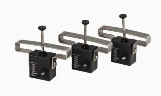
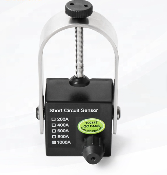
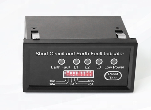
Medium voltage switchgears contain complex relays and sensing components. These electrical components monitor phase imbalance constantly. A zero-sequence current transformer detects physical leakage currents. When a fault occurs, the electromagnetic field changes rapidly. The secondary winding registers an induced current signal. A mechanical indicator or light bulb signals this event. For instance, engineers install a Panel mounted Paddle Type Short circuit Fault Indicator inside panels. This device displays mechanical flags when high current flows. Operators quickly spot the colored flags on the door. Sensing devices must withstand harsh electrical transient environments. High-voltage spikes can damage sensitive electronics inside controllers. Robust shielding prevents electromagnetic interference from disrupting signals. Therefore, physical design determines the long-term reliability of sensors. Manufacturers test these mechanisms under simulated grid stress conditions. Selecting robust parts reduces maintenance costs over decades.
Crucial Electrical Ratings For Switchgear Grid Protection
System designers analyze specific grid properties to select sensors. For example, system voltage determines the required insulation level. Engineers must specify the earth fault indicator rcd based on the network configuration. Grounding systems vary between direct grounding and high resistance configurations. This variation alters the expected earth fault current amplitudes. Low resistance networks create massive earth fault currents. Conversely, isolated grids show extremely tiny capacitive leakage currents. Protection units must accommodate these specific electrical variables. Incorrect trip settings trigger nuisance tripping during standard operations. Proper threshold adjustments prevent unnecessary power cuts. We present key technical specifications in the database below. Engineers compare these ratings to match their unique hardware. Appropriate equipment secures switchgears from sudden insulation degradation.
| System Rating | Trip Threshold | Response Time | Reset Method |
|---|---|---|---|
| 12 kV Switchgear | 10 A to 100 A | 40 milliseconds | Automatic Self-Reset |
| 24 kV Switchgear | 20 A to 160 A | 50 milliseconds | Manual Push Button |
| 40.5 kV Switchgear | 30 A to 200 A | 60 milliseconds | Remote Command |
Analyzing Performance Data From The Specifications Matrix
The technical matrix shows diverse current thresholds for switchgear. Lower voltage installations utilize tighter current trip thresholds. This design limits electrical damage during minor grounding faults. Higher voltage networks require wider setting ranges to prevent errors. For instance, 40.5 kilovolt grids operate with higher capacitive currents. Fast response times remain critical across all voltage classes. A forty millisecond reaction speed minimizes thermal stress on cables. Furthermore, reset methods influence substation recovery times significantly. Automatic self-resetting mechanisms restore protection quickly after transients. Manual push buttons offer physical verification for local technicians. Remote commands enable control room operators to reset systems instantly. Selecting the proper combination maximizes overall operational safety. Operators ensure smooth distribution by deploying these configurations.
Environmental Standards And Mechanical Designs
Industrial environments present severe challenges to switchgear components. Dust accumulation can cause tracking faults along busbar insulators. Moisture condensation accelerates corrosion on sensitive copper contacts. Therefore, enclosure ratings determine device longevity in factories. Sensing devices need robust sealing against moisture ingress. Outdoor substations face freeze-thaw cycles and high solar radiation. Extreme temperatures affect physical properties of plastic casings. Premium materials prevent cracking under sub-zero winter conditions. Similarly, flame-retardant materials enhance passive safety in distribution panels. Designers specify ingress protection ratings based on installation sites. We detail key environmental metrics in the technical table below. These values define the operational limits of reliable sensors. Using qualified enclosures guarantees decades of maintenance-free service.

| Parameter Type | Standard Requirement | Industrial Target |
|---|---|---|
| Ingress Protection | IP54 Rated Cabinet | IP65 Sensor Shell |
| Operating Temp | Minus 25 Celsius | Plus 70 Celsius |
| Humidity Level | 95 Percent RH | Non Condensing Area |
Deciphering Environmental Ratings For Switchgear Integration
The data table outlines crucial thermal and physical tolerances. Substations located in coastal areas require higher ingress protection. Using an earth fault indicator rcd ensures quick fault localization within damp indoor switchgear environments. Salty air accelerates metal oxidation without robust IP65 protection. High humidity levels trigger partial discharge across air gaps. Silicone gaskets maintain tight seals against chemical contaminants. Furthermore, temperature ratings must cover standard industrial ranges. Severe winter conditions can drop temperatures below freezing points. Conversely, operating switchgear cabins generate internal heat loads. Sensing electronics must function stably up to seventy degrees. Thermal stability prevents drift in trip current sensitivity values. Choosing durable housings secures critical networks from environmental failures. This careful selection prevents power interruptions during peak periods.
Essential Procedures For Physical System Installation
Correct physical installation determines overall system safety and reliability. Technicians must handle high-voltage cable assemblies with extreme care. Poor connection points introduce high electrical contact resistance. We outline key steps to install monitoring modules securely. First, operators inspect the physical dimensions of local cables. Second, engineers choose matching core-balance current transformer units. Third, installers arrange routing paths for standard sensor wiring. Proper grounding prevents static charge buildup on sensor casings. Shielded cables reduce high-frequency electrical noise from nearby busbars. We provide standard installation steps in the checklist below. Technicians follow these guidelines to complete the mounting process. This systematical method minimizes installation errors in substations. Ensuring strict compliance preserves the warranty of premium components.
- Verify cable dimensions before clamping sensors.
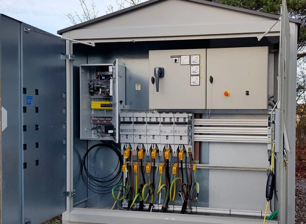
- Secure the core balance CT around all three phases.
- Route the grounding wire back through the transformer.
- Connect the signal cable to the display unit.
Detailed Assessment Of Cable Alignment Practices
The listed steps prevent common errors during site deployment. Specifically, routing the ground wire requires careful physical alignment. Grounding shields carry return currents back to the earth. These shields must pass back through the current transformer. Correct routing cancels out shielding current inside the core. Otherwise, the sensor detects a false residual current signal. False signals trigger unwanted tripping events on healthy lines. Additionally, core-balance current transformers must fit tightly around cables. Loose fittings allow external magnetic fields to distort readings. Air gaps lower measurement accuracy during low-level fault scenarios. Clamping mechanisms must resist physical vibrations over long periods. This diligent approach preserves long-term accuracy and network stability. Operators maintain high system uptime by following these procedures.
Smart Communication Protocols For Modern Grids
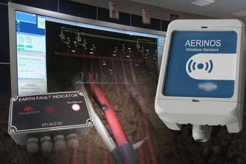
Modern power systems require constant communication between field units. Smart grids rely on digital networks to transmit telemetry data. Engineers integrate an earth fault indicator rcd that communicates with SCADA systems via Modbus. This connectivity allows remote monitoring of electrical distribution lines. Control center operators receive fault alerts within milliseconds. This rapid alarm system accelerates crew dispatch to faulty areas. RS485 serial ports provide reliable communication over long distances. Fiber optic interfaces resist high electromagnetic noise inside cabinets. Furthermore, communication protocols standardise data exchange across different brands. Interoperability prevents vendor lock-in during grid expansion phases. Smart features allow engineers to adjust trip values remotely. This remote capability decreases dangerous field maintenance visits. Selecting communicative devices represents a forward-looking utility strategy.