
Reverse Electromagnetic Lock For Switchgear: Working Principle
Reverse Electromagnetic Lock for Switchgear, with working principles, applications, selection, wiring, installation, and troubleshooting.
A Reverse Electromagnetic Lock for Switchgear helps control access and switching operations in medium-voltage electrical equipment. Its reverse locking structure accommodates specific installation positions and mechanical operating directions.
Unlike a standard electrical interlock, this device combines electromagnetic actuation with a mechanical locking mechanism. Its performance depends on the rated voltage, locking direction, mounting dimensions, and configured control logic.
Selecting the correct model helps prevent unauthorized operations and improves compatibility with the switchgear. Engineers should evaluate both the lock's mechanical structure and its electrical requirements before installation.
What Is a Reverse Electromagnetic Lock for Switchgear?
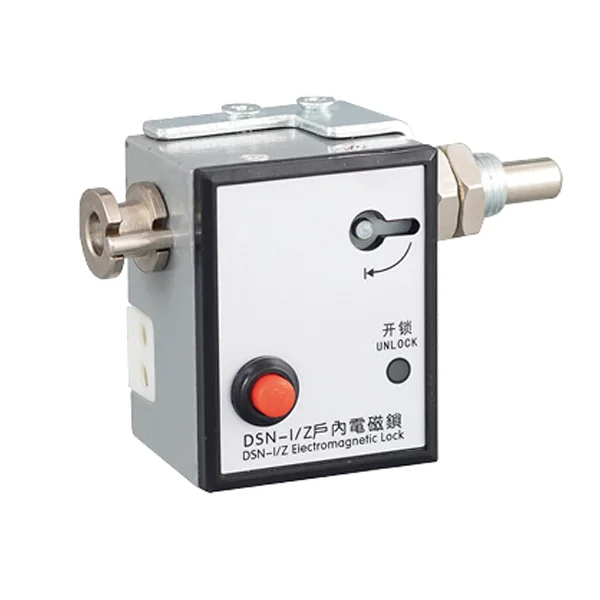
A reverse electromagnetic lock is an electrically controlled locking device used in switchgear interlocking systems. Its main components typically include an electromagnetic actuator, a locking bolt or rod, a housing, and electrical terminals.
The reverse configuration accommodates applications that require a particular locking direction or installation arrangement. This can be important when cabinet space or the operating mechanism prevents the use of a standard lock.
Common applications include switchgear cabinet doors, disconnector mechanisms, and grounding switch mechanisms. The lock restricts specific operations according to the equipment's interlocking design.
However, an electromagnetic lock is only one component of the safety system. It does not replace circuit isolation, voltage verification, grounding procedures, or other required protective measures.
How Does a Reverse Electromagnetic Lock Work?
A Reverse Electromagnetic Lock for Switchgear uses electromagnetic force to actuate a mechanical locking mechanism and control permitted operations. Its operating sequence depends on the lock's structure and the switchgear's control circuit.
Electromagnetic Actuation and Mechanical Locking
When the specified electrical conditions are met, the electromagnetic actuator moves the locking mechanism according to its design. The bolt or rod then allows or restricts the intended movement.
The reverse configuration determines the locking direction and how the mechanism fits the installation. Engineers should verify bolt travel, engagement position, and mounting dimensions to ensure compatibility with the switchgear.
The default state also varies by model. A lock should not be assumed to engage or release automatically during a power failure without confirming its specified operating behavior.
The Role of Electrical Interlocking
The lock may work with auxiliary contacts, voltage indication equipment, or other control components. These signals help the control circuit determine whether a particular operation is allowed.
For example, a switchgear design may prevent access to a compartment until specified switching conditions have been satisfied. The electromagnetic lock then enforces the permitted sequence through its mechanical action.
The control circuit must follow the approved interlocking schematic. Voltage indication alone does not establish that equipment is safely isolated.
Typical Locking and Unlocking Sequence
A typical operating sequence includes several stages:
- Initial state: The locking mechanism remains in its designed position.
- Condition verification: The control circuit checks the required interlocking signals.
- Release authorization: The mechanism permits unlocking when the specified conditions are satisfied.
- Mechanical operation: The operator performs the authorized switching or access operation.
- Relocking: The mechanism returns to its intended state according to the product design.
The actual sequence may differ between models. Always refer to the manufacturer's wiring diagram and the switchgear's approved operating procedure.
What Are the Main Types of Switchgear Interlocks?
Switchgear interlocking systems use electrical, mechanical, and electromagnetic methods to restrict incorrect operations. These methods can work independently or as part of a combined safety arrangement.
| Interlock type | Working principle | Main consideration |
|---|---|---|
| Electrical interlock | Uses control circuits and auxiliary contacts | Depends on correct wiring and control logic |
| Mechanical interlock | Uses physical blocking mechanisms | Requires compatible mechanical components |
| Electromagnetic lock | Uses an electromagnetic actuator to control locking | Requires suitable power and mounting |
| Reverse electromagnetic lock | Uses a specific reverse locking arrangement | Requires correct bolt direction and installation space |
Electrical interlocks are useful for controlling operating sequences through circuit logic. Mechanical interlocks provide physical restrictions, while electromagnetic locks allow electrical signals to control a mechanical locking mechanism.
A reverse electromagnetic lock is not automatically safer than other designs. Its suitability depends on the required locking direction, installation conditions, and overall interlocking arrangement.
Where Are Reverse Electromagnetic Locks Used in Switchgear?
Reverse electromagnetic locks are used where access or switching operations must follow a defined sequence. Their application depends on the cabinet structure and the mechanism being controlled.
Switchgear Cabinet Doors
A lock can restrict access to a designated compartment until the required conditions are satisfied. This helps reduce the risk of opening a compartment at an inappropriate stage of operation.
Installation accuracy is important because the bolt must align with the door's locking point. Misalignment can prevent engagement even when the electrical control circuit works correctly.
Disconnector Mechanisms
Disconnectors establish specific switching configurations within electrical installations. An interlocking system can prevent certain operations until the required conditions have been met.
The electromagnetic lock must match the disconnector mechanism's travel and operating direction. Its release logic must also correspond to the approved switching sequence.
Grounding Switch Mechanisms
Grounding switch operations require particular attention because incorrect switching can create serious electrical hazards. An electromagnetic lock can help restrict operations according to the configured interlocking conditions.
However, the lock cannot independently confirm that a circuit is de-energized. Electrical isolation and verification must follow the applicable safety procedures.
OEM and Retrofit Projects
Original equipment manufacturers may specify reverse electromagnetic locks when designing cabinets with particular mounting or locking requirements. Retrofit projects may need replacement devices that fit existing mechanisms.
In both cases, engineers should compare the original drawings, rated voltage, mounting dimensions, and locking direction. Similar product names do not guarantee mechanical or electrical compatibility.
How to Select a Reverse Electromagnetic Lock for Switchgear
Selecting a suitable lock requires checking the electrical specifications, mechanical structure, and interlocking requirements. A mismatch in any of these areas can cause installation difficulties or unreliable operation.
Check the Operating Voltage
Confirm the rated voltage and whether the actuator requires AC or DC power. The selected model must match the control supply available in the switchgear.
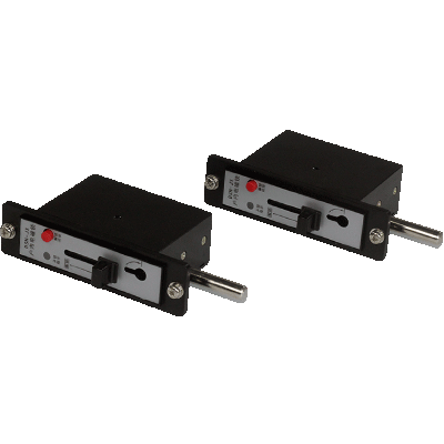
Some DSN-EM configurations offer AC/DC 110/220 V and DC 24/48 V options. These are model-specific specifications, so engineers should verify the exact rating before ordering.
Confirm the Locking Direction and Dimensions
Check the required bolt direction, mounting holes, installation depth, and mechanical travel. The reverse configuration must match the cabinet's available space and the intended engagement point.
Insufficient clearance or incorrect alignment can cause incomplete locking or mechanical friction. Compare the manufacturer's dimensional drawing with the actual installation before approving the model.
Match the Interlocking Requirements
Identify the conditions that must be satisfied before unlocking. Depending on the system design, these may involve auxiliary contacts, voltage indication, or the positions of switching mechanisms.
The lock's control circuit must support the approved operating sequence. Do not select a product based solely on its voltage rating or physical appearance.
Review Environmental Conditions and Documentation
Check the operating temperature, humidity, installation environment, and applicable protection requirements. These factors may affect the suitability of the selected model.
Before procurement, request the product datasheet, dimensional drawing, wiring diagram, and installation instructions. This documentation helps engineers verify compatibility and prepare for commissioning.
How to Install and Wire a Reverse Electromagnetic Lock
Correct installation requires both mechanical alignment and appropriate electrical connections. The manufacturer's instructions and the approved switchgear drawings should determine the installation procedure.
Mechanical Installation
Check the mounting holes, bolt direction, available clearance, and required mechanical travel. Secure the lock in the specified position and confirm that the bolt engages correctly.
Incorrect alignment can cause binding, incomplete engagement, or premature wear. Avoid modifying the mounting structure without confirming that the change is permitted by the equipment design.
Electrical Wiring
Connect the lock according to its model-specific wiring diagram. Verify the supply voltage, AC/DC requirements, terminal assignments, and control-circuit connections before energizing the equipment.
Where auxiliary contacts or voltage indication signals are used, confirm that each signal connects to the intended control logic. Terminal assignments and release conditions should never be assumed to be identical across different models.
The DSN-EM Reverse Electromagnetic Lock for Switchgear provides a product reference for checking the reverse locking structure and model-specific installation requirements.
Verify the Control Logic
Compare the completed wiring with the approved interlocking schematic. Confirm that each release condition corresponds to the intended operating state.
Functional testing should verify both permitted and restricted operations under approved test conditions. Protective interlocks must not be bypassed to force the lock to operate.
Common Problems with Reverse Electromagnetic Locks
Operating problems may result from electrical faults, mechanical misalignment, or incorrect control logic. The following checks help identify common causes.
| Problem | Possible cause | Recommended check |
|---|---|---|
| Lock will not release | Incorrect voltage, missing control signal, or mechanical obstruction | Check the supply and release conditions |
| Lock will not engage | Misalignment or insufficient travel | Inspect mounting and bolt alignment |
| Incorrect operating sequence | Wiring or control logic error | Review the approved schematic |
| Intermittent operation | Loose connections or unstable supply | Check electrical connections and supply stability |
| Replacement does not fit | Incompatible dimensions or locking direction | Compare the technical drawings |
Lock Fails to Release
Check whether the required control conditions are present and verify the supply voltage against the manufacturer's specifications. Inspect the wiring for loose connections or incorrect terminal assignments.
If the electrical circuit is correct, examine the mechanical mechanism for obstruction or misalignment. Do not force the bolt or bypass the interlock to gain access.
Lock Does Not Engage Correctly
Check the bolt's engagement point, mechanical travel, and mounting position. Even a small alignment error can prevent the locking mechanism from reaching its intended position.
If the problem continues, compare the installed device with the approved dimensional drawing. An incompatible lock should be replaced with a suitable model rather than modified without authorization.
Incorrect Interlocking Sequence
An incorrect sequence may indicate a wiring error, unsuitable auxiliary contacts, or a mismatch between the lock and the control system.
Review the interlocking schematic and verify the intended function of each signal. Qualified personnel should resolve discrepancies before returning the equipment to service.
How to Test a Reverse Electromagnetic Lock Safely
Functional testing checks whether the lock operates according to its design and the switchgear's approved interlocking sequence. Testing must follow the manufacturer's instructions and applicable site procedures.
1. Establish a safe working condition. Follow the required isolation, lockout/tagout, and electrical verification procedures.
2. Inspect the installation. Check mounting hardware, bolt alignment, wiring, and visible mechanical condition.
3. Verify electrical parameters. Confirm that the supply and connections match the product specifications.
4. Test the operating sequence. Verify locking and unlocking under approved test conditions.
5. Check restricted operations. Confirm that prohibited operations remain blocked under the specified conditions.
6. Record the results. Document abnormal behavior and correct faults before returning the equipment to service.
A functional test does not independently prove electrical isolation. Never apply conflicting control signals or force the mechanism unless the approved test procedure explicitly permits the action.
FAQs About Reverse Electromagnetic Locks for Switchgear
What Is the Difference Between a Reverse and a Standard Electromagnetic Lock?
The main difference is the mechanical locking arrangement and its suitability for a specific installation. A reverse electromagnetic lock accommodates particular bolt directions or mounting requirements. A standard model may use a different mechanical configuration. Before selecting either type, compare the dimensions, rated voltage, mechanical travel, and release logic. The product name alone does not establish the lock's default state or safety performance.
What Voltage Does a Reverse Electromagnetic Lock Require?
The required voltage depends on the specific model. Some configurations support different AC or DC ratings, but these values are not universal. Check the product datasheet and confirm compatibility with the cabinet's control supply. Also verify the terminal assignments and release conditions before installation. Applying an incompatible voltage can prevent correct operation or damage the actuator.
Can a Reverse Electromagnetic Lock Work with a VDIS?
Yes, if the lock and control system support the required integration. A Voltage Detecting and Indicating System (VDIS) can provide voltage presence information for the interlocking circuit. The actual connections and release conditions depend on the approved system design. Voltage indication alone does not prove that equipment is safely isolated, so the required isolation and verification procedures remain essential.
What Should Be Checked Before Replacing an Existing Lock?
Verify the mounting dimensions, bolt direction, rated voltage, terminal arrangement, and interlocking logic. A replacement with a similar appearance may have different mechanical travel or release conditions. Review the original drawings and the replacement manufacturer's documentation before ordering. After installation, qualified personnel should verify the locking sequence and confirm that the intended interlocking functions operate correctly.
What Happens If the Power Supply Fails?
The lock's behavior during a power failure depends on its mechanical design and control system. Some mechanisms may remain in their existing position, while others may change state according to their construction. Engineers should confirm the specified power-failure behavior in the product documentation. The switchgear's safety procedures must account for this behavior rather than assuming that every electromagnetic lock automatically locks or unlocks.
Conclusion
A reverse electromagnetic lock helps control access and switching operations when its mechanical structure matches the switchgear design. Correct selection requires checking the rated voltage, locking direction, mounting dimensions, and interlocking logic.
Proper installation and functional testing help identify compatibility problems before commissioning. Following the manufacturer's documentation and approved safety procedures supports reliable operation throughout the equipment's service life.