What Makes A Good Switchgear Voltage Indicator Factory?
Switchgear voltage indicator factory quality relies on accurate sensing, insulation design, testing, compliance, and production control.
Why Does Factory Capability Matter for Voltage Indication?
A switchgear voltage indicator factory must control electrical and mechanical details together. Medium-voltage switchgear operates under demanding insulation conditions. Voltage indicators connect closely with the primary circuit. Their sensing elements must provide stable signals without weakening insulation performance. The display must remain clear during normal operation. Connection points must also support suitable testing procedures. Poor dimensional control can create installation problems inside compact compartments. Incorrect sensing characteristics can produce unreliable indications. Material selection also affects temperature stability and electrical performance. Buyers therefore need more than a competitive unit price. They need evidence of controlled design and repeatable production. A capable supplier should explain sensing principles, voltage ranges, installation methods, and testing procedures. Those details provide a practical basis for evaluating technical competence before purchasing.
How Does Voltage Sensing Technology Affect Indicator Performance?
A switchgear voltage indicator factory should understand the electrical behavior behind voltage sensing. Many medium-voltage systems use capacitive coupling from the primary circuit. A coupling element transfers a reduced electrical signal toward the indicator. The system then activates visual indicators for individual phases. Engineering teams must control capacitance, insulation distance, electrode geometry, and signal thresholds. These factors can affect indication stability under different operating conditions. Compact switchgear creates additional design constraints. Internal conductors and grounded metalwork can influence electric fields. Cable positions may also change the coupling environment. Engineers should therefore combine electrical calculations with mechanical design. Prototype validation should follow the initial design stage. Production drawings should also remain under revision control. This approach reduces differences between approved samples and mass-produced units.
Which Components Require the Closest Quality Control?
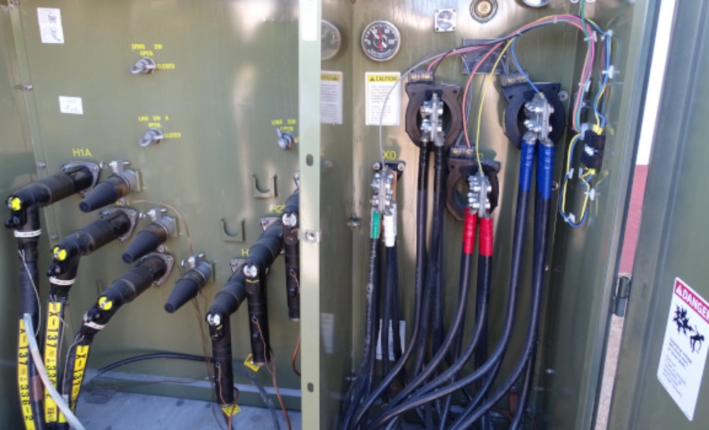
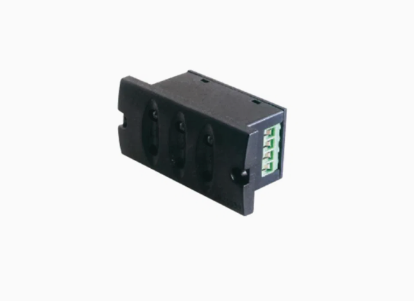
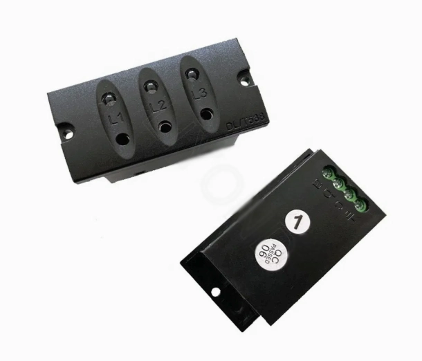
A switchgear voltage indicator factory should control every component that affects electrical performance. The sensing element forms the interface with the energized circuit. Insulating parts maintain dielectric separation from grounded structures. Electronic components process the received signal. LEDs or similar visual elements communicate the voltage condition. Connectors provide interfaces for testing and phase comparison. Each component should have defined acceptance criteria. Incoming inspection should verify dimensions, materials, electrical characteristics, and appearance. Assembly workers should follow controlled wiring procedures. Incorrect cable routing can affect capacitive behavior. Loose connections can also create intermittent indications. Production records should identify critical component batches. Traceability becomes important when customers report abnormal behavior. Engineers can then identify affected batches and review related test results. This process supports corrective action and reduces repeated quality problems.
What Production Tests Should Confirm Product Quality?
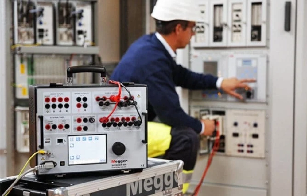
A switchgear voltage indicator factory should combine electrical testing with manufacturing inspection. Visual checks can confirm correct assembly and phase identification. Functional tests should verify each phase responds correctly. Electrical tests should use defined acceptance limits. Insulation-related checks should follow the applicable design requirements. Test equipment must remain within its calibration period. Operators should record actual results rather than relying on visual confirmation. Failed units should enter a controlled rework process. Reworked products should receive required retesting before release. Testing should also reflect the approved product configuration. Generic testing cannot always represent a customized design. IEC 62271-213:2021 covers voltage detecting and indicating systems for high-voltage equipment. It includes coupling systems for connection to live parts. The standard replaced earlier VPIS-related requirements within its scope.
| Quality Control Stage | Main Purpose | Typical Evidence |
|---|---|---|
| Incoming inspection | Verify critical materials and components | Inspection records and material data |
| Assembly inspection | Confirm correct wiring and installation | Work instructions and inspection results |
| Functional testing | Verify phase indication response | Recorded test results |
| Electrical testing | Confirm specified electrical behavior | Measured values and acceptance limits |
| Final inspection | Confirm product release requirements | Final inspection report |
| Traceability review | Link products with production records | Batch and serial records |
How Should Testing Records Support Batch Consistency?
A reliable testing system should connect every result with a specific production unit. Serial numbers, batch codes, and production dates can support this process. Operators should record actual measurements when numerical limits apply. Failed units should remain separated from accepted products. Reworked units should receive the required retests. Calibration records should identify the equipment used for measurement. This information allows engineers to investigate quality problems more efficiently. Production data can also reveal gradual process changes. For example, repeated deviations may indicate component variation or assembly problems. Buyers can request sample records during supplier audits. They can compare results from different production batches. Consistent documentation provides stronger evidence than a single laboratory report. A factory should also retain controlled drawings and revision histories. These records help confirm that tested products match the current production version.
How Should a Switchgear Voltage Indicator Factory Handle Compliance?
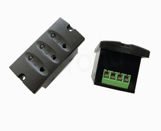
A switchgear voltage indicator factory should identify the correct standards for each application. IEC 62271-213:2021 now covers voltage detecting and indicating systems. It includes capacitive, resistive, and other coupling technologies within its scope. IEC 62271-215:2021 addresses phase comparators used with these systems. Earlier IEC 62271-206:2011 specifically covered voltage presence indicating systems above 1 kV and up to 52 kV. That edition was later replaced by IEC 62271-213:2021. Buyers should therefore check the current standard applicable to their project. Destination markets can also impose additional requirements. Compliance documents should identify the tested product configuration. They should also show the relevant test scope. A generic certificate may not cover every customized design. Proper documentation connects technical requirements with the actual product supplied.
What Should Buyers Check During a Factory Audit?
A factory audit should examine engineering, production, testing, and traceability together. Buyers should request physical evidence for each important process. The following checklist can help structure an on-site evaluation.
- Review current electrical drawings and engineering revisions.
- Check incoming inspection procedures for critical components.
- Inspect assembly stations and controlled wiring processes.
- Verify testing equipment and calibration records.
- Review failed-product handling and corrective actions.
- Check batch identification and production traceability.
- Confirm packaging methods for transportation protection.
How Does Customization Affect Electrical and Mechanical Design?
A switchgear voltage indicator factory often needs to customize both mechanical and electrical features. Common changes include mounting dimensions, cable lengths, connectors, display arrangements, and sensing configurations. Installation space can be limited inside compact switchgear compartments. Cable routing may also influence capacitive behavior. Engineers should confirm rated voltage and frequency before selecting sensing components. They should review mounting positions against the customer's drawings. Grounded metal structures require consideration during electrical design. A customized unit should pass design validation before mass production. Small changes can alter the electric field around sensing elements. The approved sample should therefore represent the final production configuration. Engineering changes should also receive documented review. This process reduces the risk of field modifications. It also helps maintain consistent performance across repeat orders. OEM development should treat each significant customization as an engineered configuration.
| Customization Area | Typical Requirement | Recommended Verification |
|---|---|---|
| Rated voltage | Match the switchgear system | Specification review |
| Mounting dimensions | Fit the available panel space | Dimensional inspection |
| Phase connections | Match the circuit arrangement | Wiring verification |
| Cable harness | Follow internal routing requirements | Assembly inspection |
| Indicator position | Maintain clear operator visibility | Functional inspection |
| Testing interface | Support required phase comparison | Interface verification |
Why Should Customized Designs Receive Separate Validation?
Customized designs need separate validation because physical changes can affect electrical behavior. A longer cable can change parasitic capacitance. A different mounting position can modify the surrounding electric field. Nearby grounded structures can also influence signal coupling. Engineers should therefore validate the complete configuration. Sample testing should use representative switchgear interfaces whenever practical. Validation records should identify the drawing revision and test configuration. Production teams should freeze the approved design before batch manufacturing. Later engineering changes should trigger documented technical review. This method limits uncontrolled variation between customer samples and production units. It also provides purchasing teams with stronger qualification evidence. A capable supplier should explain why each change does or does not require retesting. This level of technical communication reduces uncertainty during OEM projects. It also creates a clearer basis for approving repeat orders.
What Does a Real Switchgear Project Reveal About Factory Quality?
Real switchgear projects show why voltage indication requires early technical coordination. A documented 2026 service case involving RM6 medium-voltage switchgear reported challenges with field installation of VPIS systems. The case highlighted wire harnessing, testing, verification, and validation as important installation considerations. Factory-fitted indicators can reduce some field integration work when specifications are confirmed during ordering. This example shows why engineers should define mounting, wiring, sensing, and testing requirements before production. A voltage indicator should not become an afterthought after switchgear assembly. Factory validation should cover the complete approved configuration before shipment. Early coordination can reduce field modifications and wiring errors. It can also simplify commissioning procedures at the installation site. For buyers, this practical experience provides useful evidence when assessing a supplier's engineering and production capabilities.
How Important Are Capacity and Traceability for Large Orders?
Production capacity matters when switchgear projects require repeated deliveries. However, stated monthly output does not prove manufacturing stability. Buyers should examine production planning, component availability, testing resources, and inspection capacity. A factory may have sufficient assembly space but limited testing equipment. That imbalance can create delays during large orders. Traceability provides another important layer of control. Each batch should connect finished products with production records. Critical components should also remain traceable where practical. Engineering changes should have clear revision numbers and effective dates. When customers report a problem, traceability can accelerate investigation. Teams can identify affected batches and review their test records. Production data can reveal recurring defects or process drift. Buyers should therefore evaluate capacity together with quality infrastructure. Stable output requires people, equipment, materials, procedures, and records to operate consistently.
What Should Buyers Request Before Placing an Order?
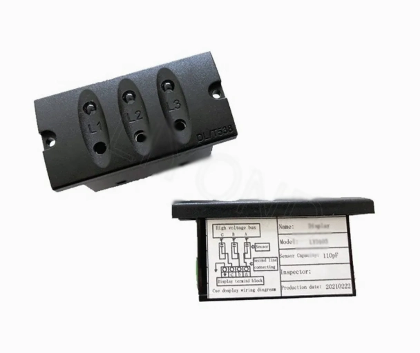
Before placing an order, buyers should request technical documents that support direct comparison. A switchgear voltage indicator factory should provide clear information for the exact proposed configuration. Buyers should review product drawings, electrical specifications, test reports, and quality records before approval. The DXN8D High Voltage Presence Indicator can be evaluated through its sensing method, installation interface, and required verification procedures. These details help buyers confirm whether the proposed product matches the switchgear design. Technical documents should also identify applicable voltage ranges and connection requirements. Sample approval should precede mass production when the design includes significant customization.
Clear engineering-change procedures can prevent later production differences. Buyers should also confirm testing methods and acceptance criteria before placing repeat orders. Packaging requirements should receive attention because electrical components can face transport damage. Storage conditions should also match the selected materials. Clear documentation improves communication between purchasing, engineering, and quality teams. It also reduces the risk of approving one configuration and receiving another. Strong suppliers should answer technical questions with measurable information. This approach creates a more reliable basis for long-term B2B cooperation.
| Document | Purpose | Buyer Verification |
|---|---|---|
| Product drawing | Confirms dimensions and interfaces | Compare with switchgear drawings |
| Technical specification | Defines electrical parameters | Check voltage and frequency |
| Test report | Shows verified product performance | Check configuration and test scope |
| Material information | Supports component evaluation | Review critical insulation materials |
| Quality records | Shows process control | Check inspection and traceability |
| OEM information | Clarifies customization capability | Review engineering-change control |
How Can Buyers Evaluate Factory Reliability?
A supplier evaluation should focus on documented capabilities rather than marketing claims. Engineering experience is one important factor. Testing capability is another. Production traceability provides evidence of process discipline. Customization experience matters when switchgear has unusual interfaces. A Fixed Voltage Presence Indicating System can also provide a useful reference for evaluating technical integration. Suppliers should explain its sensing principle, installation requirements, and applicable testing procedures. Communication quality also affects technical projects. Suppliers should answer technical questions with drawings, specifications, and test evidence. They should identify limitations instead of promising every configuration without validation. Buyers can compare approved samples with production documentation. Differences between samples and batch products require investigation. These factors provide a practical framework for supplier qualification. No single indicator proves long-term reliability.
FAQ
What Does a Switchgear Voltage Indicator Do?
A voltage indicator provides a visual indication related to the voltage condition of a switchgear circuit. Many medium-voltage systems use capacitive coupling to obtain the required signal. Individual phase indicators commonly show the voltage condition of each phase. The system helps operators identify voltage presence during normal operating procedures. However, an illuminated or extinguished indicator should not automatically replace an approved safety procedure. Schneider Electric distinguishes VPIS functions from systems designed to verify voltage absence. The actual application depends on voltage level, switchgear design, and applicable requirements. Buyers should confirm the intended function before selecting a product. Technical documents should state the sensing principle, operating range, connection method, and testing requirements. Clear functional definitions help prevent incorrect application during switchgear integration.
What Tests Should Voltage Indicators Pass?
Testing requirements depend on the product design and applicable standards. Routine production checks should verify correct assembly and phase indication. Functional testing should confirm that each phase responds correctly. Electrical testing should use calibrated equipment and defined acceptance limits. Design validation may require additional tests for the complete system. IEC 62271-213:2021 applies to voltage detecting and indicating systems for high-voltage equipment. The standard covers coupling systems and defined interfaces for these systems. Buyers should request reports identifying the tested configuration. Generic certificates may not demonstrate compliance for every customized product. Production records also matter because prototype testing cannot represent every future batch. A strong quality system therefore combines design validation with routine manufacturing inspection. This combination provides better evidence of repeatability and controlled production.
Can a Factory Customize Voltage Indicators for Different Switchgear?
Yes, factories can customize voltage indicators for different switchgear configurations. Common changes include mounting dimensions, cable harnesses, connectors, display layouts, and sensing arrangements. However, customization should involve engineering review rather than dimensional changes alone. Altering electrode geometry can affect capacitive behavior. Changing cable routing can also influence the electrical signal. Nearby grounded structures may modify the surrounding electric field. Engineers should review the complete configuration before production. Prototype validation can confirm whether the customized design meets specified requirements. Buyers should provide rated voltage, frequency, installation drawings, and connection requirements during quotation. Sample approval should precede mass production when the design differs materially. Clear engineering-change procedures are also important for repeat orders. They help ensure that later production continues to match the approved configuration and tested performance.