How Is VDIS Used In MV Switchgear?
VDIS for MV switchgear provides voltage presence indication, phase monitoring, and safer decisions during medium-voltage switching.
What Role Does VDIS Play In MV Switchgear?
VDIS for MV switchgear provides visible information about voltage presence inside medium-voltage equipment. Operators can check phase conditions through an external indication interface. This function reduces the need to approach energized compartments during routine status checks. VDIS typically supports three-phase voltage presence indication through capacitive sensing interfaces. However, it does not replace isolation procedures or approved voltage testing equipment. Engineers should therefore treat VDIS as one safety-related information layer. Its value depends on correct electrical integration and reliable component installation. Medium-voltage switchgear often operates in demanding industrial environments. Dust, moisture, temperature changes, and mechanical vibration can affect auxiliary components. Proper specification therefore matters from the initial switchgear design stage. A suitable system should match the switchgear voltage class, sensing arrangement, and operating environment.
How Does VDIS for MV switchgear Detect Voltage?
VDIS detects voltage through capacitive coupling between the primary conductor and sensing circuit. Capacitive interfaces connect to suitable points within the medium-voltage circuit. These interfaces transfer a small sensing signal to the indication system. The sensing circuit then evaluates whether voltage exists on each monitored phase. Operators see the resulting status through dedicated visual indicators. This approach keeps the indication interface electrically separated from direct operator contact. Engineers must consider the electrical characteristics of the sensing interface carefully. Rated voltage, system frequency, phase arrangement, and insulation requirements all affect compatibility. The sensing path also requires appropriate insulation and physical separation. Incorrect component selection can produce weak, unstable, or misleading indications. Therefore, manufacturers should verify the complete sensing chain during design validation. The indicator itself should never become the only basis for declaring equipment safe.
Which Components Form A VDIS Assembly?
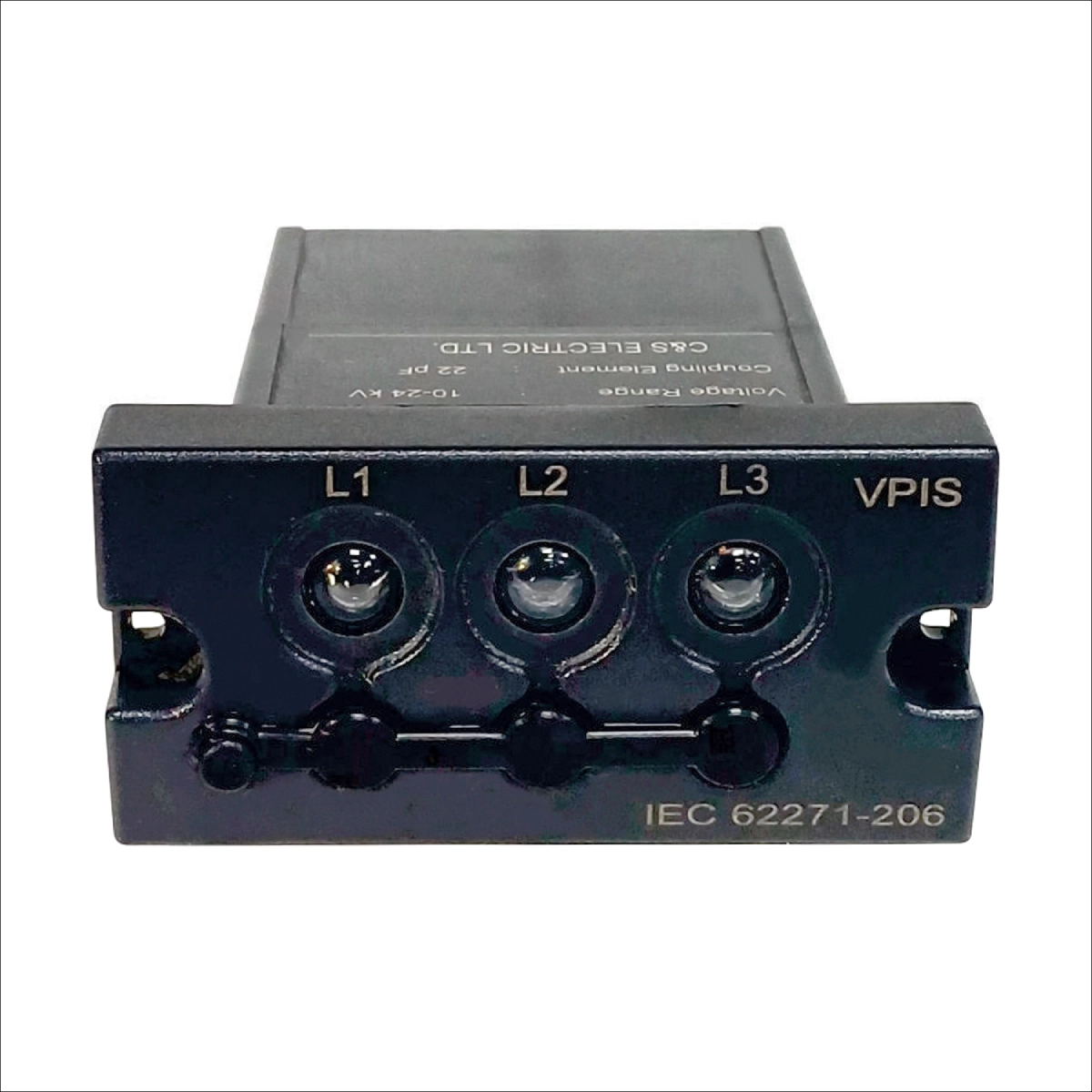
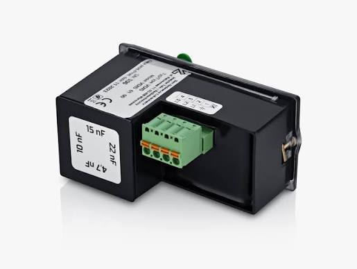
A typical VDIS arrangement contains several coordinated electrical and mechanical elements. Capacitive interfaces connect the sensing system with selected primary circuit points. Connection conductors then carry the sensing signals toward the indication section. Dedicated indicator elements provide visible phase-status information to operators. A 54×32mm Switchgear Voltage Indicator can provide a compact interface for phase-status indication. Some arrangements also include test points for checking indicator functionality. The enclosure design must protect these components from accidental contact and environmental exposure. Switchgear manufacturers should define mounting locations before finalizing internal wiring. Clear terminal identification helps technicians trace each phase during commissioning. Mechanical fixing also matters because vibration can loosen connections over time. Component spacing should support insulation coordination within the intended voltage environment. Documentation should identify each sensing connection and its corresponding phase. This information simplifies factory testing, field commissioning, and later maintenance. A coordinated assembly therefore provides more dependable status information than isolated components.
| VDIS Component | Primary Function | Design Consideration |
|---|---|---|
| Capacitive interface | Provides voltage sensing input | Must match the intended primary circuit arrangement |
| Sensing connection | Transfers the detection signal | Requires correct phase identification and insulation |
| Indicator unit | Displays voltage presence | Needs clear phase identification and suitable visibility |
| Test interface | Supports functional verification | Should remain accessible for authorized testing |
Why Do Individual Phase Indicators Matter?
Individual phase indication in VDIS for MV switchgear gives operators more information than a single general status signal. Each phase can display its own voltage-presence condition. This arrangement helps identify differences between the three phase circuits. For example, one phase may show no indication while the other phases remain active. Such a condition requires investigation before switching or maintenance activities continue. Technicians can compare the displayed phase status with the intended circuit configuration. They can also inspect sensing connections when the displayed condition appears abnormal. Phase-specific information becomes particularly useful during commissioning and troubleshooting. It helps technicians isolate possible wiring errors without immediately opening energized compartments. However, an indicator condition does not prove complete electrical isolation. Authorized personnel must follow the site's established isolation and verification procedures. Clear phase labeling further reduces confusion during inspection. Consequently, phase-specific indication provides useful operational information within a broader electrical safety process.
What Safety Decisions Can VDIS Support?
VDIS can support several preliminary decisions during normal switchgear operation. Operators can check whether monitored phases appear energized before performing authorized switching activities. Maintenance personnel can also observe voltage-status information from an accessible indication point. This visibility can reduce unnecessary interaction with primary circuit compartments. Nevertheless, the indication should work alongside mechanical and electrical interlocking arrangements. Isolation, discharge, and grounding procedures remain separate safety requirements. Personnel should follow the equipment's approved operating sequence before accessing restricted areas. VDIS also cannot determine every hazardous electrical condition within a switchgear assembly. For example, stored energy or an incorrectly configured circuit can create separate risks. Operators should therefore interpret indication results within the complete switching procedure. Proper labeling helps connect the displayed status with the relevant feeder or circuit. Regular functional checks further improve confidence in the displayed information. The system provides operational visibility, rather than replacing established electrical safety controls.
How Does VDIS for MV switchgear Integrate With The Cabinet?
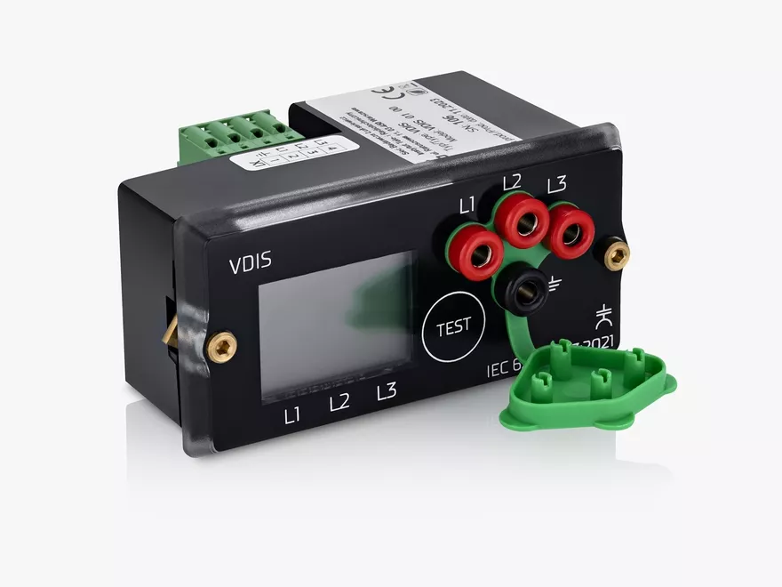
VDIS for MV switchgear requires coordinated integration with the primary and secondary systems. Engineers first identify suitable voltage sensing points within the primary circuit. They then establish the required sensing connections for each monitored phase. Secondary wiring must remain separated from circuits that could introduce unwanted interference. Internal routing should also protect sensing conductors from mechanical damage. Designers should maintain suitable clearance around terminals and other energized components. The switchgear enclosure must provide adequate protection against accidental contact. Engineers should also consider cable bending radius and connector accessibility. Door-mounted indicators require flexible routing that can withstand repeated door movement. Fixed indicators need clear viewing angles from the normal operator position. Each connection should receive durable identification during assembly. Factory documentation should record the actual connection arrangement used in production. Proper integration allows commissioning technicians to verify the complete indication chain efficiently.
Which Installation Factors Affect VDIS Performance?
Several installation conditions can influence the reliability of voltage presence indication. The rated system voltage must correspond with the sensing interface requirements. Frequency also matters because sensing circuits operate within specified electrical conditions. Phase connections require accurate identification from the beginning of assembly. Loose terminals can increase contact resistance and create intermittent indication problems. Poor cable routing may expose sensing conductors to mechanical stress or accidental damage. Moisture can affect insulation performance around terminals and sensing interfaces. Dust accumulation may also create contamination paths across exposed insulating surfaces. Temperature extremes can affect component characteristics and enclosure conditions. Mechanical vibration presents another concern in industrial switchgear installations. Technicians should secure connections according to the manufacturer's specified installation method. Environmental protection should match the actual switchgear service location. These checks help prevent installation-related faults from being mistaken for indicator failures.
How Is VDIS Tested Before MV Switchgear Commissioning?
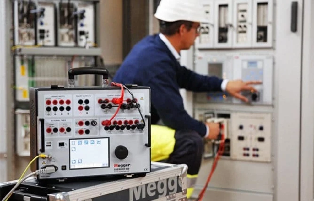
Commissioning should verify both the electrical connections and the visible indication response. Technicians can begin by checking phase identification against approved electrical drawings. Each sensing connection should correspond with its intended primary circuit phase. The indicator should then respond correctly under controlled test conditions. Functional checks should cover every available phase rather than relying on one indication. Technicians should record unexpected or inconsistent responses during testing. They can then inspect terminals, connectors, sensing interfaces, and internal wiring. A second verification should confirm that corrective work restored normal indication. Documentation should capture test conditions, results, and identified corrective actions. Factory acceptance testing can reveal wiring issues before equipment reaches the installation site. Site commissioning provides another opportunity to confirm the complete system after transportation. Combining both stages creates stronger quality control. Reliable testing also provides useful baseline information for future maintenance activities.
What Does A Real MV Switchgear VDIS Application Look Like?
A practical case can involve an industrial plant commissioning a new medium-voltage distribution lineup. During functional testing, technicians found that one phase indicator remained inactive. The other two phase indicators responded normally under the same controlled conditions. Engineers first confirmed that the primary circuit had the expected configuration. They then checked the corresponding sensing connection and terminal identification. Inspection revealed an incorrectly routed connection near the indicator interface. The physical component itself showed no visible damage during the inspection. Technicians corrected the connection and repeated the phase-by-phase functional test. All three indicators then produced the expected voltage-presence response. The team recorded the wiring correction in the commissioning documentation. This case illustrates why troubleshooting should follow the complete sensing path. Replacing the indicator immediately could have failed to address the actual problem. Systematic verification can distinguish component faults from installation errors. Such testing also protects manufacturers from unnecessary replacement costs during commissioning.
How Does VDIS Differ From Other Voltage Indication Methods?
VDIS for MV switchgear primarily provides voltage-presence information rather than detailed electrical measurement. A measurement instrument can provide numerical voltage values under suitable test conditions. Protection equipment performs another function by detecting defined electrical faults. VDIS instead gives operators a clear indication of monitored voltage status. An Inductive High Voltage Indicator Display can serve a related indication role within suitable electrical monitoring arrangements. This distinction matters when engineers define the required switchgear functions. A project may require indication, measurement, protection, or several functions together. Designers should avoid treating these systems as interchangeable. VDIS can complement protection relays and other monitoring equipment within the same assembly. It can also provide a convenient local status interface for authorized personnel. However, the indicator does not calculate fault current or replace protection settings. It does not independently establish that a circuit contains zero hazardous energy. Engineers should define each function according to the operational requirement. Clear functional boundaries make system specifications easier to verify.
What Procurement Checks Matter For VDIS Systems?
B2B buyers should evaluate the complete technical specification before selecting a VDIS system. The procurement process should match the indication system with the intended switchgear design. Important checks include:
- Rated system voltage and frequency
- Three-phase sensing configuration
- Capacitive interface compatibility
- Indicator visibility and phase identification
- Mounting and connection requirements
- Environmental operating conditions
- Insulation and electrical coordination requirements
- Testing procedures and technical documentation
These checks help buyers compare products using relevant engineering requirements. A low purchase price alone cannot establish suitability for medium-voltage equipment. Procurement teams should request dimensional drawings and connection information before approval. Test procedures should also remain available for factory and site verification. Documentation should identify applicable operating limits and installation requirements. Engineers can then confirm compatibility with the actual cabinet design. This approach reduces specification gaps between the component supplier and switchgear manufacturer. It also creates clearer responsibilities during commissioning. Careful procurement therefore supports both technical reliability and production consistency.
How Can VDIS Reliability Be Maintained Over Time?
Long-term reliability depends on both component condition and connection integrity. Maintenance teams should inspect accessible indicator components during scheduled switchgear servicing. Visual checks can identify damaged housings, loose connections, or unusual contamination. Technicians should also review historical test records for repeated indication abnormalities. Moisture exposure deserves attention when equipment operates in humid environments. Dust and industrial contamination may require additional enclosure inspection. Connection checks should follow the equipment manufacturer's approved maintenance procedures. Functional testing can confirm that each phase continues to produce the expected indication. Any abnormal result should trigger a controlled troubleshooting process. Maintenance personnel should record corrective actions and replacement components. Consistent records help identify recurring installation or environmental problems. Replacement planning should consider component availability and the switchgear service schedule. Preventive maintenance can therefore reduce unexpected indication failures.
What Should Engineers Verify Before Selecting VDIS?
Engineers should evaluate VDIS as part of the complete MV switchgear architecture. The first check involves system voltage, frequency, and phase configuration. Next, designers should verify the sensing interface and primary circuit arrangement. Mechanical dimensions must match the available installation space. Electrical clearances should remain suitable for the intended voltage environment. Engineers should also confirm indicator visibility from the operator's normal position. Environmental conditions should match the component's specified operating range. Testing requirements should remain practical for both factory and site commissioning. Documentation should provide enough information for installation and maintenance teams. A suitable system should integrate cleanly with the switchgear's existing safety functions. Engineers should also confirm that indication remains clearly distinguishable for each phase.
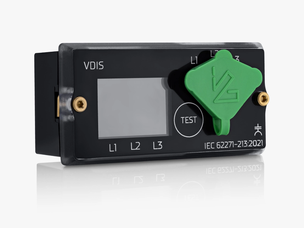
These checks create a technical basis for consistent selection. Proper evaluation helps ensure that voltage-status information remains useful throughout equipment operation.
FAQ
Can VDIS Replace Voltage Testing During MV Maintenance?
VDIS cannot replace formal voltage verification during maintenance procedures. The system provides an indication of voltage presence through its sensing arrangement. Formal testing uses approved procedures and suitable test equipment for the specific task. Maintenance personnel should follow the switchgear manufacturer's safety instructions and site procedures. Isolation and grounding requirements also remain separate from indication functions. Therefore, operators should treat VDIS as an operational status aid. They should not interpret an inactive indicator as independent proof of zero voltage. Correct maintenance practice requires a complete isolation and verification sequence. The exact procedure depends on the equipment design and applicable electrical safety rules. VDIS adds useful visibility, but it does not eliminate the need for controlled electrical verification.
Does VDIS Indicate Voltage On Every Phase?
Many VDIS arrangements provide individual indication for three monitored phases. Each indicator corresponds to a dedicated sensing connection within the switchgear. This arrangement allows operators to observe phase-specific voltage-presence conditions. However, the exact configuration depends on the switchgear design and selected system. Engineers should confirm the number of monitored phases during specification and procurement. Installation errors can also cause one phase to display incorrectly. Technicians should therefore verify each indication during factory testing and commissioning. An inactive indicator may result from the circuit condition or a sensing connection issue. Troubleshooting should examine the complete sensing path before replacing components. Clear phase labeling makes these checks easier and reduces wiring mistakes. Proper testing confirms whether each displayed condition matches the intended circuit state.
Where Is VDIS Installed In MV Switchgear?
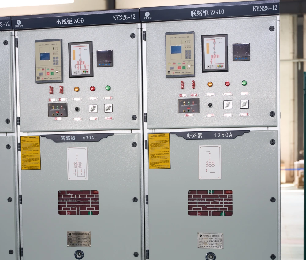
VDIS components normally integrate with the switchgear's voltage sensing and indication arrangement. Capacitive interfaces connect to appropriate points associated with the primary circuit. The indication unit may sit on an accessible panel or compartment interface. Its position should allow authorized operators to view phase status clearly. Internal sensing connections require suitable insulation and mechanical protection. Designers should also consider access for factory testing and future maintenance. Door-mounted arrangements require careful attention to cable movement and mechanical strain. Fixed panel arrangements can simplify routing when the cabinet layout permits. The final location depends on the switchgear architecture, voltage class, and sensing design. Engineers should document the exact mounting and connection arrangement before production. Proper placement improves visibility while maintaining the required separation from energized components.