Why Are IR Inspection Windows Important?
IR inspection windows improve electrical safety, simplify thermal monitoring, reduce downtime, and support reliable predictive maintenance.
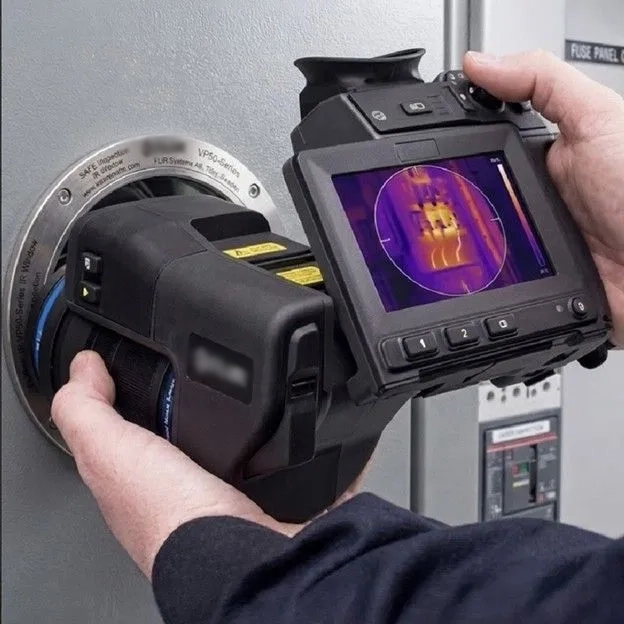
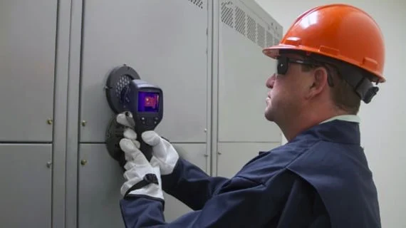
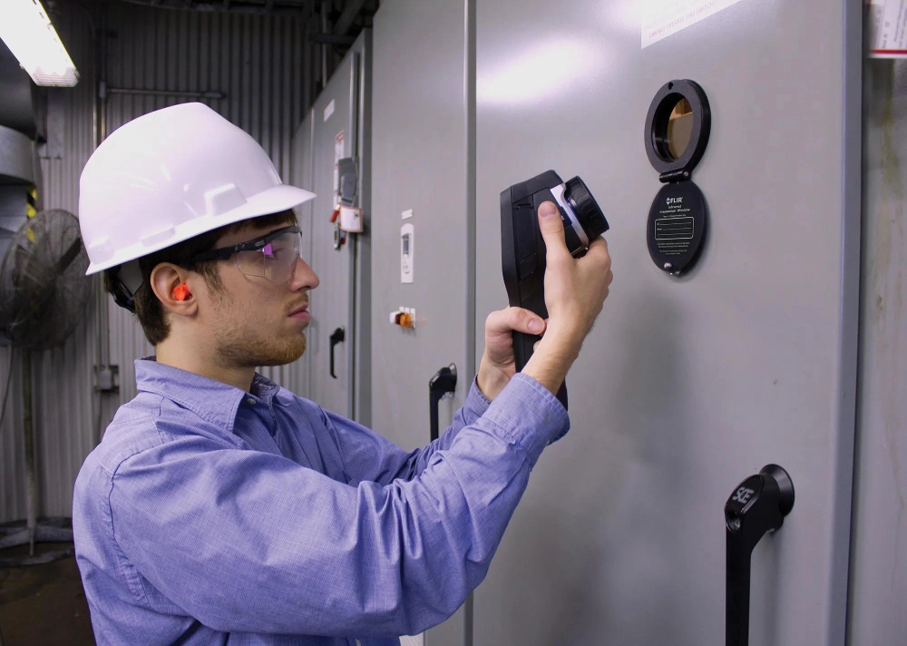
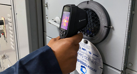
IR inspection windows provide safer access for thermal inspections inside energized electrical equipment. Technicians can capture infrared images without opening cabinet doors during routine inspections. This approach reduces direct exposure to energized components and supports faster maintenance decisions. Thermal cameras can identify abnormal temperature patterns around connections, conductors, breakers, and other critical components. Early temperature changes often indicate developing electrical problems before visible damage appears. Regular inspections also create useful thermal records for maintenance teams. These records support comparisons between phases, components, and inspection periods. Proper window placement improves the camera's view of important heat sources. However, window selection requires more than choosing a convenient opening size. Material, viewing angle, installation method, environmental conditions, and cabinet layout all affect inspection performance.
Why Are IR Inspection Windows Important for Electrical Maintenance?
Fixed thermal observation points can improve routine electrical maintenance significantly. Technicians can inspect energized equipment without repeatedly opening cabinet doors. This reduces unnecessary physical access to internal electrical components. Thermal cameras can capture images from consistent positions during scheduled inspections. Consistency matters because technicians can compare current readings with previous thermal images. Maintenance teams can identify gradual temperature changes before they become severe equipment problems. Fixed inspection points also simplify inspection routes across multiple electrical cabinets. Facilities can establish standardized procedures for similar equipment and operating conditions. However, thermal imaging requires professional interpretation and suitable measurement practices. Load current, ambient temperature, emissivity, and reflection can influence readings. A properly designed inspection point therefore supports better data collection without replacing established electrical maintenance procedures.
How Do Thermal Inspection Systems Improve Electrical Safety?
Opening an energized electrical cabinet can expose workers to serious electrical hazards. These hazards can include energized conductors, arc flash, and unexpected equipment conditions. An infrared viewing point allows thermal imaging from outside the enclosure. Technicians can keep the cabinet closed during many routine thermal inspections. This reduces unnecessary exposure to internal energized components. The approach also helps maintenance teams perform inspections with less physical access. However, the window does not eliminate electrical hazards from the workplace. Qualified personnel must still follow applicable safety procedures and approach boundaries. Appropriate personal protective equipment remains necessary when required by working conditions. NFPA 70E provides electrical safety work practices for many United States workplaces. Site-specific procedures may impose additional requirements. Safe inspection therefore depends on both suitable equipment and disciplined operating practices.
How Does Infrared Thermal Imaging Detect Electrical Faults?
Infrared cameras detect thermal radiation from surfaces and convert it into temperature-related images. Electrical resistance causes energy to dissipate as heat when current passes through connections. Poor connections can therefore produce localized heating under normal operating loads. Loose terminals, corrosion, and damaged contact surfaces can increase resistance. Overloaded conductors can also produce elevated temperatures across larger areas. Uneven phase temperatures may indicate load imbalance or connection problems. Technicians should compare similar components whenever operating conditions permit. A single hot spot does not automatically identify one specific failure mechanism. Load current, ambient conditions, emissivity, and reflected radiation can affect readings. Thermal patterns provide stronger diagnostic evidence when technicians combine them with electrical data. Historical images also help identify changes over time. Professional analysis converts temperature differences into useful maintenance decisions. IR inspection windows help technicians access these thermal targets while maintaining consistent viewing positions during recurring inspections.
Which Electrical Components Need Infrared Inspection?
Different electrical components produce different thermal patterns during operation. Busbar joints deserve close attention because high current can amplify connection resistance. Circuit breaker terminals can develop abnormal heating when connections deteriorate. Cable terminations may show localized temperature increases around poorly secured connections. Disconnects can develop heat near contact points and cable interfaces. Fuses may reveal uneven loading through temperature differences between similar devices. Transformers can require carefully positioned viewing points around accessible connection areas. Technicians should prioritize components according to electrical load and failure consequences. The following table summarizes common inspection targets and thermal concerns.
| Component | Primary Inspection Area | Potential Thermal Concern |
|---|---|---|
| Busbars | Joints and connections | Loose or resistive connections |
| Circuit Breakers | Terminals and cable connections | Contact or termination heating |
| Cable Terminations | Lugs and connection points | Loose connections or overload |
| Disconnects | Contacts and terminals | High-resistance contact points |
| Fuses | Fuse bodies and terminals | Uneven loading or poor connections |
| Transformers | Accessible connection areas | Abnormal connection temperatures |
Each component requires an inspection position that provides a clear thermal view. Internal barriers can hide critical connections from poorly positioned windows. Technicians should therefore map important heat sources before installation. High-current connections often deserve priority because resistance-related heating can increase rapidly. Phase comparisons can also reveal abnormalities that individual temperature readings might miss. A thermal inspection becomes more valuable when the same component receives repeated observations. Maintenance teams can establish normal thermal patterns under known load conditions. Future deviations can then receive additional technical attention. Component location, cabinet depth, and camera field of view should guide inspection planning. The objective is useful coverage rather than simply installing the maximum number of windows.
What Design Features Should Buyers Consider?
Selection should begin with the intended inspection target and cabinet configuration. Window dimensions need to provide adequate access for the thermal camera. Viewing angles should account for internal barriers and component orientation. Mounting systems must provide stable installation throughout normal equipment operation. Environmental protection becomes important in dusty, humid, corrosive, or outdoor locations. Temperature resistance should match expected operating conditions around the electrical enclosure. Optical characteristics should also match the thermal camera used by technicians. A 100A Infrared Temperature Measurement Window may suit applications requiring a defined measurement configuration. Buyers should verify its technical specifications against the actual cabinet design. Installation dimensions also need compatibility with enclosure construction. Product documentation should provide material information, mounting requirements, and operating limitations. Selecting by appearance or opening size alone can result in inadequate thermal coverage. IR inspection windows should therefore match the cabinet layout, camera specifications, and intended measurement points.
How Does Infrared Window Material Affect Thermal Imaging?
Window material directly affects infrared radiation reaching the thermal camera. Different materials transmit infrared wavelengths with different levels of efficiency. Technicians should match material characteristics with the camera's operating wavelength range. Material thickness can also influence infrared transmission and image quality. Surface contamination may reduce transmission and weaken visible thermal patterns. Scratches, dust, and residue can create additional measurement concerns during repeated inspections. Regular cleaning helps preserve optical performance when the application permits cleaning. Technicians should follow supplier cleaning recommendations to avoid surface damage. Environmental exposure can also affect long-term material performance. High humidity, chemicals, and temperature cycling may influence certain window constructions. Buyers should request documented optical and environmental specifications before procurement. Suitable material selection supports repeatable thermal measurements. Poor optical compatibility can reduce the value of an otherwise well-positioned inspection window.
Where Should Infrared Viewing Points Be Installed?
Window positioning determines which internal components technicians can inspect successfully. The selected location should provide a direct or practical optical path toward critical heat sources. Busbar joints may sit behind barriers that restrict the camera's viewing angle. Breakers and cable terminals can also occupy different depths inside the same cabinet. Technicians should evaluate the camera's field of view before finalizing mounting positions. Inspection distance can affect image framing and temperature measurement quality. Multiple smaller windows may provide better coverage than one large opening. This approach can target separate components from appropriate angles. Cabinet structure must also support secure installation without weakening critical enclosure areas. New cabinet designs offer greater flexibility because inspection points can enter the engineering process early. Existing cabinets require additional evaluation because internal structures may restrict suitable locations. Proper positioning creates repeatable views of the most important thermal targets.
What Should Technicians Check During Thermal Inspections?
Technicians can use a consistent checklist during scheduled thermal inspections:
- Compare similar phases under comparable load conditions.
- Check busbar joints for localized temperature increases.
- Inspect breaker terminals and cable connection points.
- Look for unusual temperature differences between similar components.
- Record thermal images for future comparisons.
- Verify abnormal readings against electrical operating data.
- Check window surfaces for contamination or physical damage.
A structured inspection process improves consistency between technicians and inspection periods. Thermal images should contain enough context to identify the inspected component. Teams should record load conditions and ambient temperatures whenever practical. These details improve comparisons between different inspection periods. Technicians should also consider emissivity and reflected radiation during measurement. A visible hot area does not always indicate an electrical fault. Manufacturer specifications can provide useful reference information for specific equipment. Historical thermal images can reveal whether a condition remains stable or changes over time. Abnormal findings may require electrical testing or controlled shutdown procedures. Consistent documentation turns individual thermal images into useful maintenance records. The inspection point supports access, while professional analysis determines the appropriate response.
How Can IR Inspection Windows Reduce Maintenance Downtime?
Routine thermal inspection can become faster when technicians avoid opening electrical enclosures. Reduced cabinet access can simplify preparation for scheduled thermal surveys. Fixed inspection points also make recurring inspections easier to organize. Technicians can target the same component from the same approximate position. This improves comparison between current and historical thermal images. Faster inspections can help facilities increase monitoring frequency without equivalent increases in maintenance effort. Early detection may also allow planned corrective work before equipment failure causes an unexpected shutdown. However, thermal inspection cannot replace electrical testing or physical maintenance. Serious abnormalities may still require controlled equipment shutdowns. Maintenance teams should use thermal results to prioritize further investigation. Facilities can then allocate maintenance resources according to equipment condition. This approach supports more efficient planning and reduces unnecessary disruption. Consistent inspection access makes thermal monitoring a practical part of routine maintenance programs.
How Do Thermal Inspection Systems Support Predictive Maintenance?
Predictive maintenance depends on reliable condition data collected over time. Thermal monitoring can provide valuable information about electrical connection performance. Fixed viewing points improve repeatability across multiple inspection periods. Maintenance teams can establish baseline temperatures for normally operating equipment. Later images can reveal temperature changes that deserve further investigation. Useful records can include inspection dates, equipment loads, ambient conditions, and thermal images. Consistent camera settings also improve the quality of historical comparisons. A gradual temperature increase may indicate developing deterioration. Sudden changes may require faster investigation, especially on critical equipment. Phase-to-phase comparisons can provide additional diagnostic information. Maintenance teams can combine thermal trends with electrical measurements and equipment history. This creates a broader condition assessment rather than relying on one temperature reading. Regular monitoring can therefore support better maintenance scheduling and asset management decisions. IR inspection windows can strengthen this process by providing fixed observation points for repeatable thermal data collection.
What Standards and Installation Practices Matter?
Electrical inspection equipment should match the safety and construction requirements of its installation. Buyers should review applicable electrical safety rules and enclosure specifications. NFPA 70E addresses electrical safety work practices in many United States workplaces. Other IEC or national standards may apply according to equipment type and market. Installation requirements can vary with enclosure design and environmental conditions. Mechanical strength should remain adequate after creating an inspection opening. Sealing performance may also matter in dusty or moisture-prone environments. Incorrect installation can compromise enclosure protection and mechanical integrity. Suppliers should provide clear technical documentation for dimensions and mounting requirements. Buyers should also verify material properties and applicable testing information. Qualified personnel should handle installation when electrical safety requirements demand professional work. Standards provide an important framework, but application-specific engineering remains necessary. Correct installation helps maintain both inspection performance and enclosure functionality.
How Should Buyers Select the Right Thermal Inspection Windows?
Buyers should evaluate inspection coverage, optical performance, durability, and installation compatibility together. The lowest purchase price does not always provide the best long-term value. A durable window has limited value if it cannot provide a useful thermal view. Similarly, excellent optical performance cannot compensate for poor positioning. Buyers should identify critical components before comparing product specifications. Cabinet layout should determine the number and location of inspection points. Camera compatibility should also receive careful technical review. Environmental conditions can influence material and sealing requirements. The following table provides a practical selection framework.
| Selection Factor | Information to Confirm | Practical Impact |
|---|---|---|
| Inspection Target | Components requiring thermal monitoring | Defines suitable viewing locations |
| Viewing Area | Camera field of view and target distance | Determines thermal coverage |
| Material | Infrared transmission characteristics | Influences image quality |
| Cabinet Layout | Internal barriers and component depth | Affects viewing access |
| Environment | Humidity, dust, chemicals, and temperature | Affects service durability |
| Installation | Mounting dimensions and enclosure structure | Supports secure integration |
How Can Thermal Inspection Windows Improve Routine Monitoring?
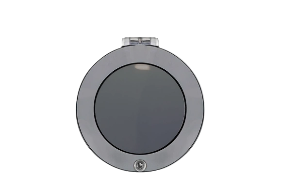
Routine monitoring becomes more effective when technicians follow consistent inspection routes. Fixed observation points reduce variation between different inspection periods. A 100F Infrared Temperature Measurement Window can support applications requiring a defined inspection configuration. Technicians should verify product specifications against the cabinet and thermal camera before installation. Operating load also deserves attention because electrical heating changes with current. A heavily loaded connection can naturally run hotter than the same connection under lighter conditions.