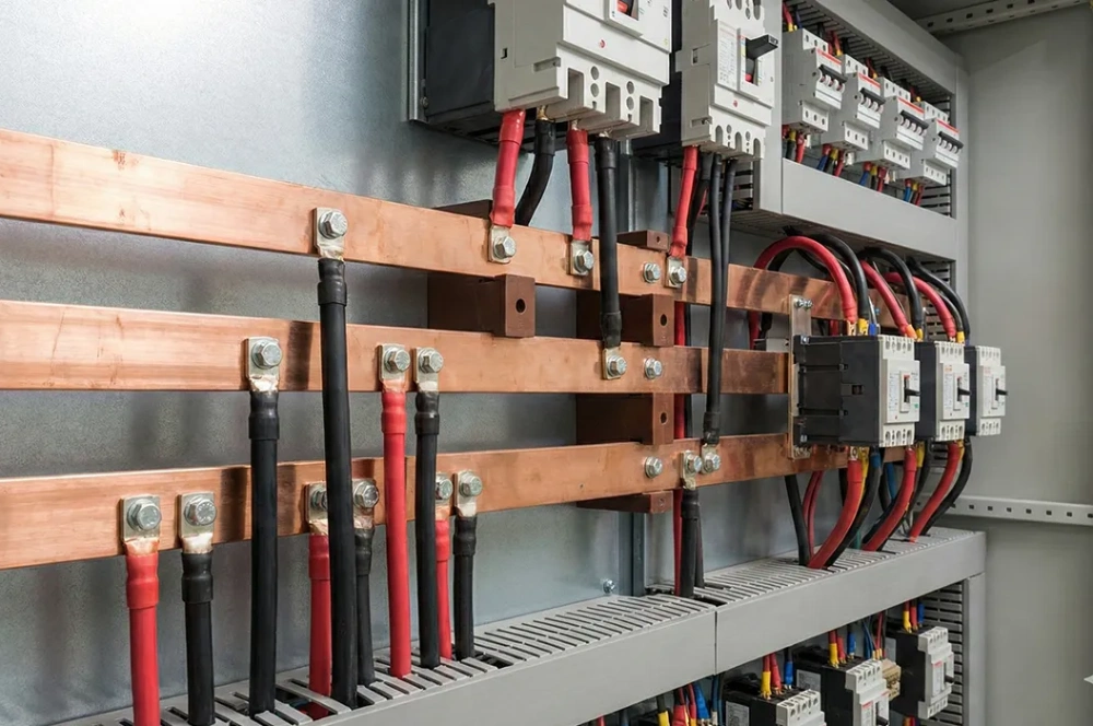
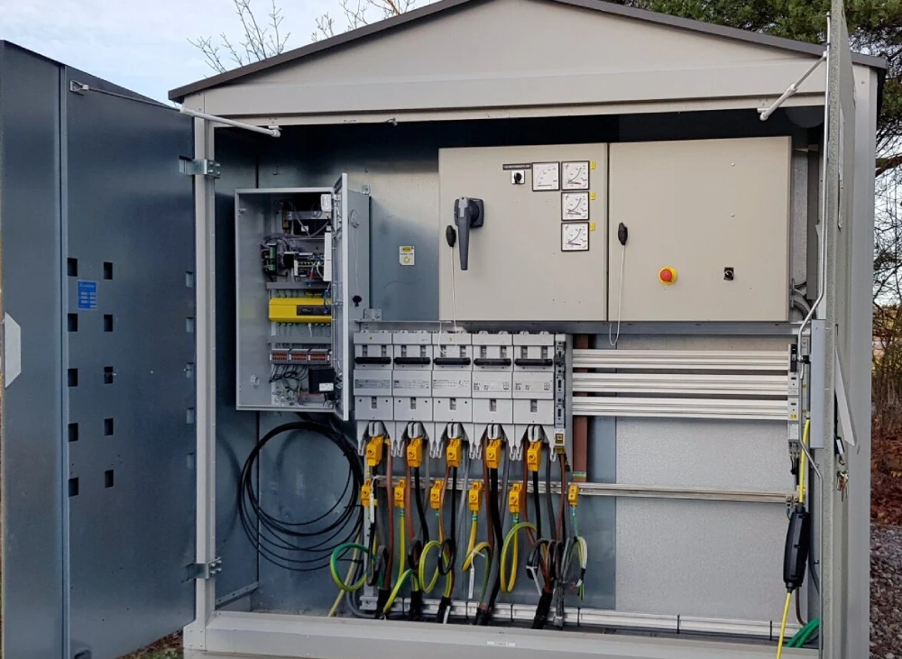
Why Use Remote Earth Fault Indicators For Large Projects?
Earth fault indicator for large projects enables faster fault location, safer maintenance, remote monitoring, and reliable power management.
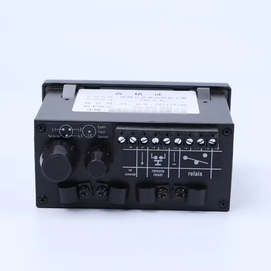
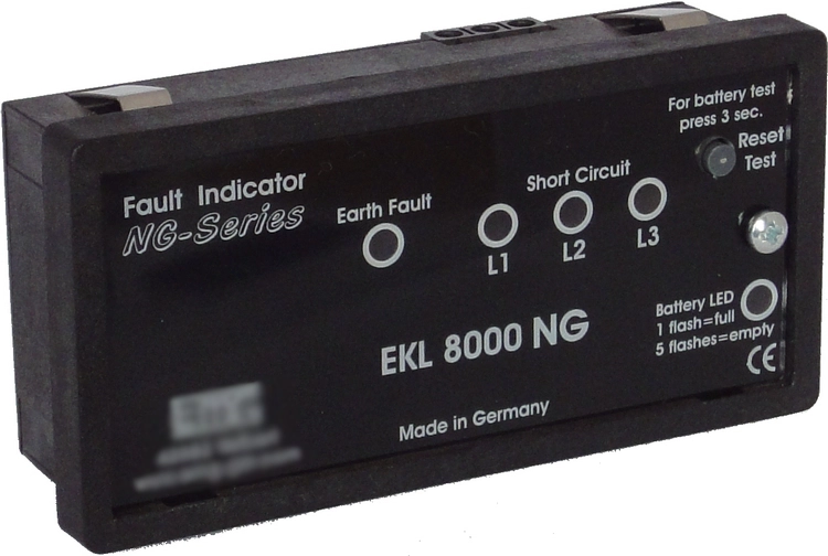
Large power projects often contain long feeders, multiple substations, and many distribution branches. These conditions make fault location more difficult than simple local networks. An earth fault can interrupt power across important loads and create extensive maintenance work. An earth fault indicator for large projects helps maintenance teams narrow the suspected fault area faster. Remote status information also reduces unnecessary field inspections across large sites. Industrial parks, transport facilities, campuses, and utility networks can benefit from this approach. Project teams should consider both electrical performance and communication reliability during selection. Installation planning also affects detection quality and operating convenience. A suitable system supports faster decisions after abnormal current conditions appear. It can therefore improve maintenance coordination while helping teams restore affected circuits more efficiently.
How Remote Fault Monitoring Improves Project Efficiency
Traditional fault inspection often requires technicians to travel between cabinets, feeders, and substations. Large sites make this process slower when cable routes extend across wide areas. Remote monitoring provides status information without requiring immediate physical inspection at every point. Technicians can review indicator states and identify likely fault sections before dispatching personnel. This approach can reduce travel time and support better allocation of maintenance resources. Communication reliability remains important because missing data can delay fault assessment. The monitoring system should match the site's network structure and environmental conditions. Project managers should also define alarm priorities before commissioning the system. Clear alarm rules help operators distinguish actual electrical events from communication issues. Remote visibility therefore supports faster coordination during both routine maintenance and unexpected outages.
Key Applications Across Large Power Networks
Large electrical installations have different feeder structures and operating priorities. Industrial facilities may require rapid fault localization because production equipment depends on continuous power. Commercial complexes often contain many buildings connected through distributed feeders. Transport facilities can also have long underground cable routes with limited physical access. Renewable energy projects may connect multiple generation areas through extensive collection networks. Each application creates different requirements for detection range, communication coverage, and installation access. Designers should map feeder sections before selecting indicator locations. They should also consider switching points and cable entry arrangements. Strategic placement creates clearer fault boundaries across the network. A well-planned layout helps maintenance teams isolate affected sections without inspecting every downstream device. This approach becomes increasingly valuable as project size and feeder complexity increase.
- Industrial parks with long production feeders
- Commercial complexes with multiple distribution branches
- Transport facilities using extensive underground cables
- Renewable energy projects with distributed collection circuits
- Critical infrastructure requiring high power continuity
Application Structure Shapes Remote Monitoring
Application design determines how many monitoring points a large electrical network may need. Long feeders usually require multiple indicators to create useful fault boundaries. Branching circuits also need careful placement because one fault can affect several downstream paths. Industrial sites may prioritize production continuity, while transport projects may prioritize restricted access. Commercial projects often need centralized information for several buildings and distribution zones. Renewable installations can require wider communication coverage across separated collection areas. Designers should map cable routes, switching locations, and equipment boundaries before installation. They should then assign clear device identifiers for every monitoring point. This structure helps operators connect remote alarms with physical circuit locations. It also makes future expansion easier when new feeders or buildings join the network.
| Application Scenario | Main Challenge | Monitoring Priority |
|---|---|---|
| Industrial parks | Long feeders and production loads | Fast fault localization |
| Commercial complexes | Many buildings and branches | Centralized status visibility |
| Transport facilities | Restricted cable access | Remote event indication |
| Renewable projects | Distributed collection circuits | Wide communication coverage |
| Critical infrastructure | High continuity requirements | Reliable fault information |
How Earth Fault Indicator for Large Projects Improves Fault Location
Fault indicators work best when designers divide long circuits into practical monitoring sections. Each indicator can provide a local status signal after detecting an abnormal earth fault condition. Remote communication then allows operators to review several locations from a central interface. This method reduces the area requiring immediate physical inspection. An earth fault indicator for large projects becomes more valuable when the network contains many branches. Operators can compare signals from different feeder sections and identify the probable fault zone. Installation spacing should reflect cable length, feeder architecture, and expected fault behavior. Detection settings also need compatibility with system grounding characteristics. Incorrect settings can create missed events or unnecessary alarms. Therefore, commissioning should include controlled testing under defined electrical conditions. Proper segmentation and calibrated detection settings create more useful information for maintenance decisions.
Technical Features That Matter Most
Technical selection should begin with electrical compatibility rather than communication features alone. Rated voltage, fault detection sensitivity, response behavior, and insulation requirements all affect performance. Communication options should match the project's existing infrastructure and operating environment. Outdoor locations may require stronger enclosure protection against moisture, dust, and temperature changes. Underground cable systems may create different installation constraints than indoor switchgear. Maintenance teams should also review indicator visibility during local inspection. Battery life matters when remote units operate independently for long periods. Alarm transmission should provide stable information during normal operation and fault events. Suppliers should document testing methods and applicable electrical standards for the proposed equipment. Buyers should also confirm installation dimensions and connection requirements before procurement. These checks reduce compatibility problems during project deployment.
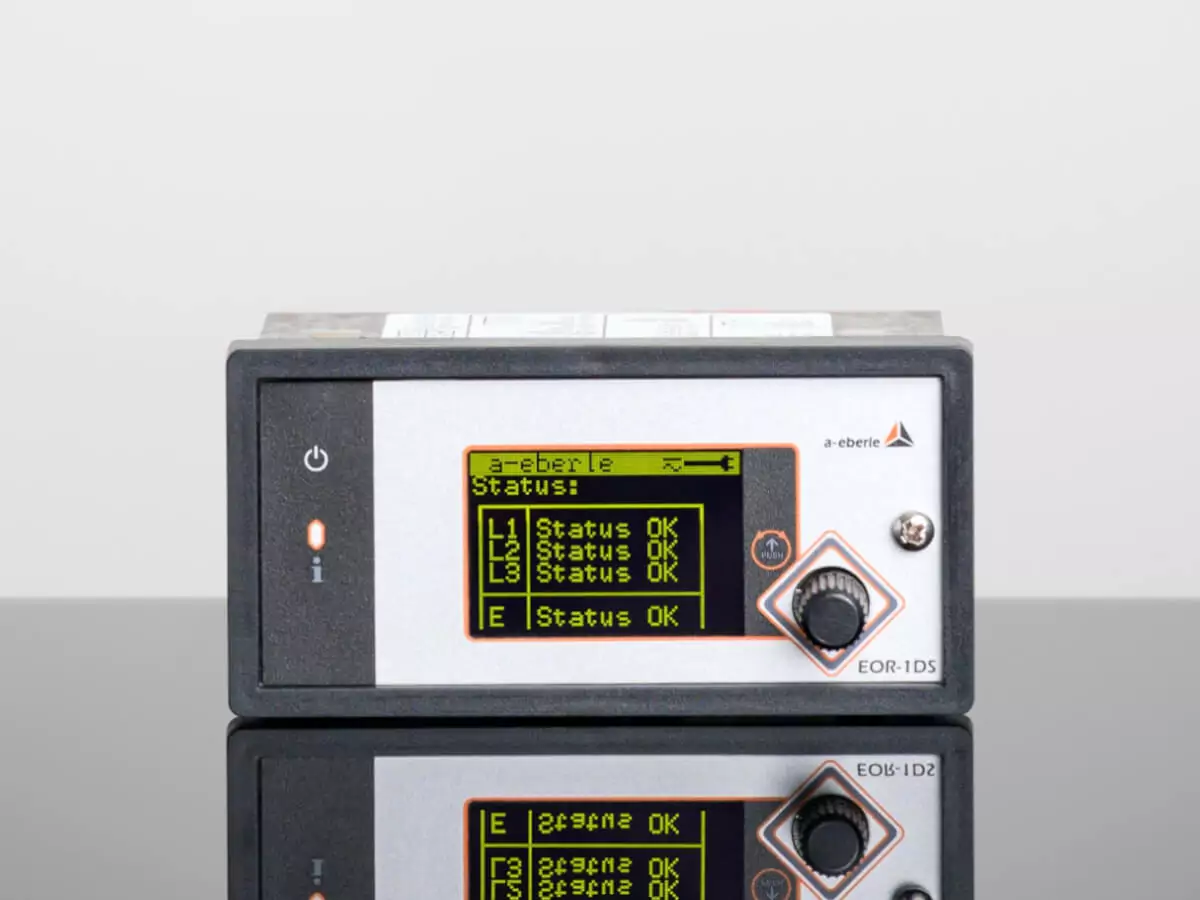
| Technical Factor | What Buyers Should Check | Project Impact |
|---|---|---|
| Detection sensitivity | Compatible fault current range | Better event recognition |
| Communication method | Coverage and network compatibility | More reliable remote monitoring |
| Enclosure protection | Moisture, dust, and temperature resistance | Improved field durability |
| Power supply | Battery or auxiliary power requirements | Longer operating continuity |
| Installation design | Mounting and cable compatibility | Easier deployment |
| Testing process | Factory and site verification | Greater commissioning confidence |
How Technical Design Affects Monitoring Accuracy
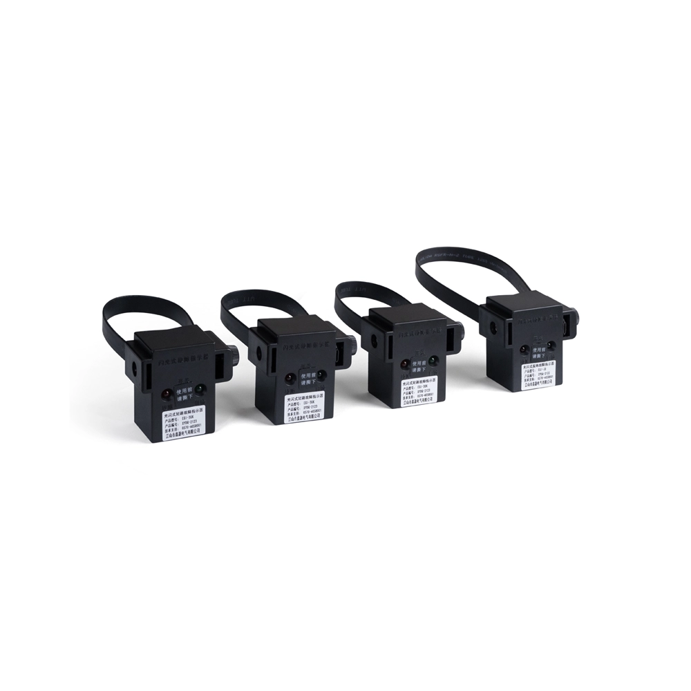
Monitoring accuracy depends on more than the indicator electronics. Sensors, installation positions, grounding conditions, and cable arrangements all influence detection behavior. Designers should verify sensor compatibility with conductor dimensions and installation methods. Poor sensor positioning can weaken signal quality or complicate maintenance access. An Integrated Indicator for Voltage Presence Grounding Fault combines voltage presence indication with grounding fault information. Such integration can reduce the number of separate monitoring components around suitable applications. However, project engineers must verify electrical ratings and functional requirements before deployment. Communication units also need stable placement to maintain reliable data transmission. Shielding, interference, and nearby equipment can affect communication performance in some installations. Site surveys should therefore identify possible electrical and physical interference sources. Careful engineering improves the consistency of information presented to operators during fault events.
How Communication Systems Support Remote Operation
Remote monitoring depends on dependable communication between field indicators and the control platform. Different projects may use wired networks, wireless links, or dedicated communication infrastructure. Wired connections can provide predictable paths where network cabling already exists. Wireless solutions may simplify deployment across areas where new communication cables are difficult to install. Network design should consider distance, obstacles, interference, and power availability. Operators also need clear rules for communication loss and delayed status updates. A communication alarm should remain distinguishable from an electrical fault alarm. Data timestamps can help maintenance teams determine whether information is current. Central platforms may also record event histories for later maintenance analysis. These records can reveal recurring fault locations and support preventive maintenance planning. Reliable communication turns individual field indicators into a coordinated monitoring network.
Why Installation Design Affects Maintenance Results
Installation planning directly affects how useful remote fault information becomes. Designers should align indicator locations with feeder sections, switching points, and maintenance boundaries. Long cable routes may require multiple monitoring points to create practical fault zones. Engineers should also reserve adequate space for sensors, communication modules, and service access. A Cable Type Short Circuit Grounding Flash Fault Indicator may suit specialized cable monitoring requirements. However, its application should match the actual cable construction and electrical protection scheme. Maintenance access deserves equal attention because technicians still need local verification after remote alarms. Labels should identify each monitoring point clearly and match the central monitoring system. Installation records should include device locations, circuit references, and communication identifiers. Accurate documentation prevents confusion during emergency maintenance. A well-designed installation therefore improves both fault localization and long-term service efficiency.
How Remote Indicators Support Safer Maintenance
Remote fault information can help technicians prepare before entering affected electrical areas. Operators can first review alarm locations and identify likely sections requiring inspection. This process reduces unnecessary movement through large electrical facilities. It also helps maintenance teams organize isolation procedures before physical work begins. Remote information should never replace required electrical safety procedures or verification steps. Technicians must still follow site rules for isolation, testing, grounding, and access control. Clear event information can nevertheless improve preparation and reduce avoidable inspection activities. Large projects benefit when maintenance teams share consistent alarm information across operating shifts. Centralized records can also support communication between control room staff and field technicians. These capabilities make remote indicators useful as part of a broader maintenance system. Their value increases when project procedures clearly define how teams respond to each alarm.
What Buyers Should Check Before Project Deployment
Procurement teams should evaluate the complete operating environment before approving a monitoring solution. Electrical ratings should match the distribution system and planned installation points. Detection characteristics should support the project's grounding method and expected fault conditions. Communication performance should match the required monitoring distance and network architecture. Buyers selecting an earth fault indicator for large projects should verify enclosure protection carefully. Protection requirements vary across indoor, outdoor, underground, and high-humidity locations. Buyers should also review installation labor, commissioning requirements, and future maintenance access. Supplier documentation should clearly describe testing, calibration, and quality control procedures. Spare parts and technical support can influence long-term operating costs. Project teams should request sample specifications and confirm compatibility before large-scale deployment. Field trials can expose communication or installation problems before full installation. A structured procurement process reduces technical uncertainty and supports consistent performance across multiple project zones.
How Project Scale Changes Maintenance Requirements
Project scale changes the economics of fault inspection and maintenance. Small facilities may tolerate manual inspection because feeder routes remain short and accessible. Large projects create higher travel distances and more inspection points. Additional substations and branches also increase the number of possible fault locations. An earth fault indicator for large projects can reduce the search area after a detected event. Remote information allows teams to prioritize locations instead of checking every feeder section equally. Maintenance managers can therefore assign personnel according to fault severity and site access. Historical event records may also help identify repeated issues in particular circuits. Over time, this information can support targeted inspections and replacement planning. Larger projects should also standardize indicator naming and alarm descriptions. Consistent data improves coordination when several teams operate different sections of the same electrical network.
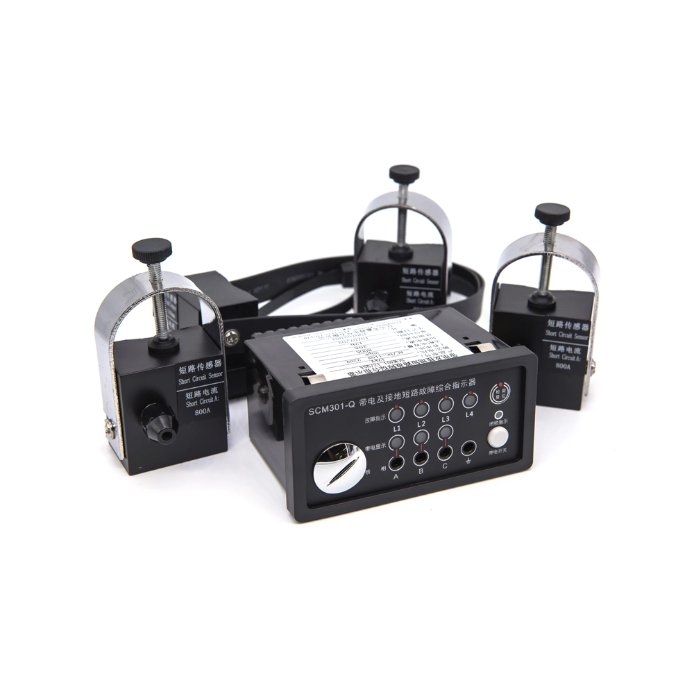
Why Remote Monitoring Creates Long-Term Project Value
Remote monitoring provides value beyond faster fault identification during individual incidents. It can improve maintenance planning, reduce unnecessary travel, and support clearer operational coordination. Centralized event records create useful information for recurring fault analysis. Maintenance teams can compare event locations, frequencies, and response times over longer operating periods. These records can support decisions about cable inspection, protection adjustments, and equipment replacement. An earth fault indicator for large projects also supports scalable monitoring when a network expands. Additional monitoring points can follow new feeders without redesigning the entire maintenance process. Project owners should therefore evaluate expansion capability during initial system selection. Reliable communication and standardized device identification make future expansion easier. Long-term value comes from combining dependable detection with organized maintenance procedures. The strongest solutions support both immediate fault response and sustained network management.