
Cable Type Fault Indicator: Working Principle And Applications
Cable type fault indicator: working principles, fault detection, installation tips, and applications in medium-voltage power networks.
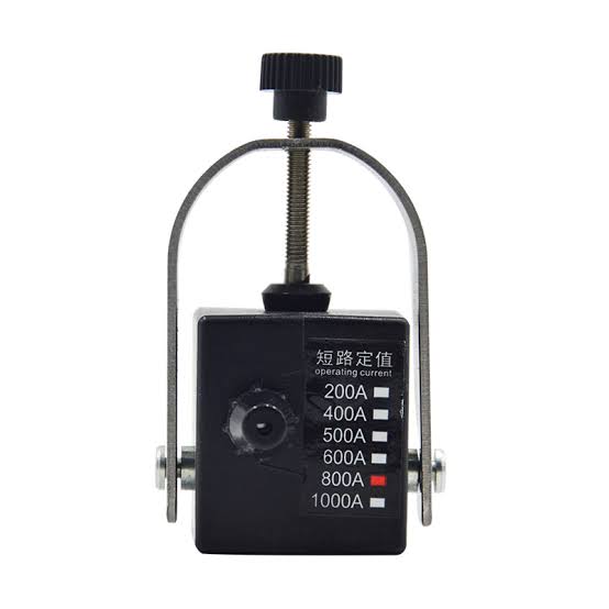
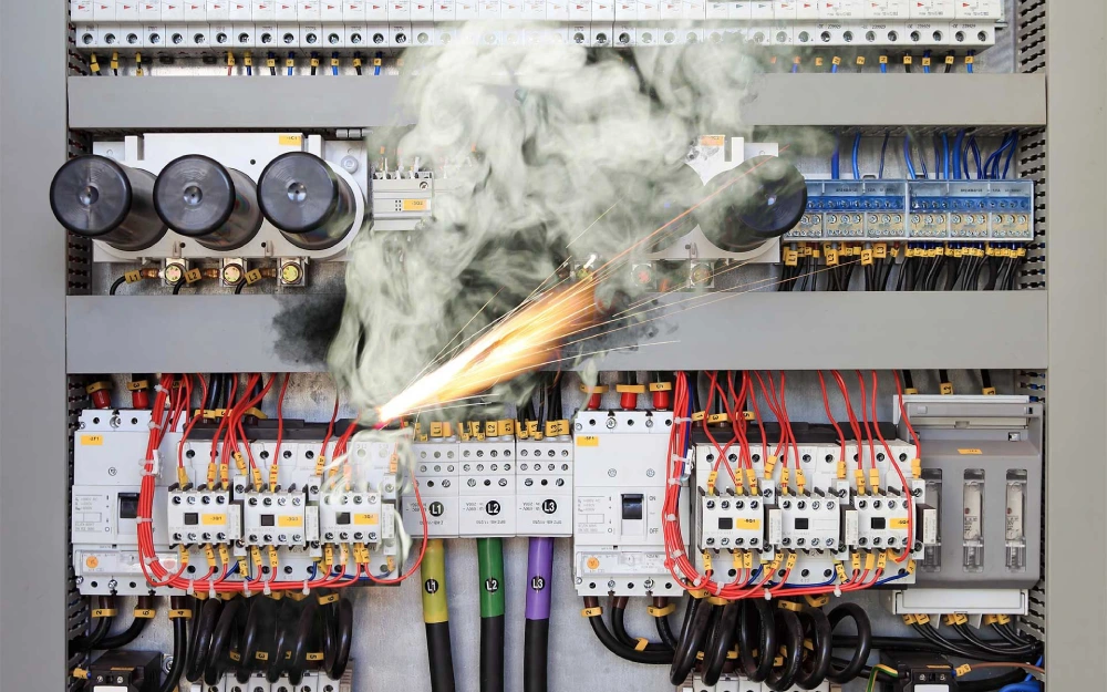
Electrical faults in underground cable networks can interrupt power distribution and complicate maintenance. A cable type fault indicator helps identify affected cable sections by detecting abnormal electrical conditions and providing visible fault signals. These devices are commonly used in medium-voltage distribution systems, ring main units, and cable branch boxes. They allow maintenance teams to narrow down fault locations without inspecting every section of a feeder. Their effectiveness depends on suitable detection technology, correct installation, and compatibility with network conditions.
What Is a Cable Type Fault Indicator?
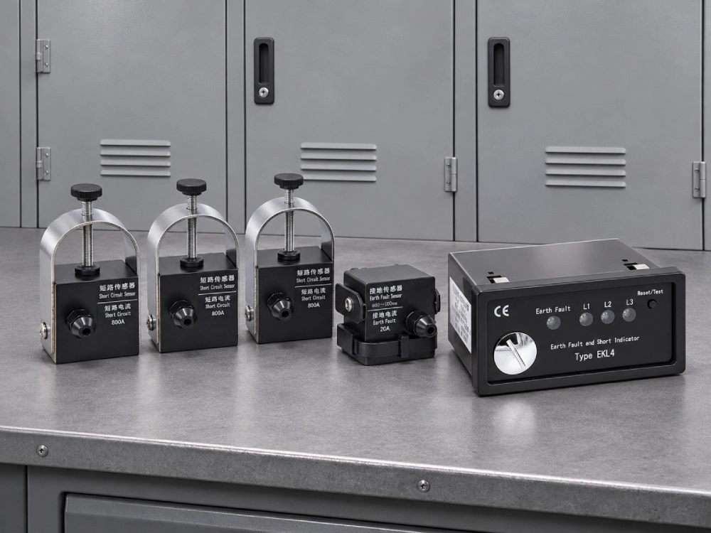
A cable type fault indicator is an electrical monitoring device designed to detect short circuits, ground faults, or both in distribution cables. It typically consists of current sensors, a signal processing unit, and an indication mechanism. Sensors monitor electrical conditions without requiring direct contact with the cable conductor. When the monitored signals meet predefined fault criteria, the device activates an alarm or visual indication. Maintenance personnel can then inspect multiple indicators along a feeder to identify the suspected faulted section. Unlike specialized cable fault locators, these devices generally identify fault passage rather than the precise physical location of insulation damage.
How Does a Cable Type Fault Indicator Work?
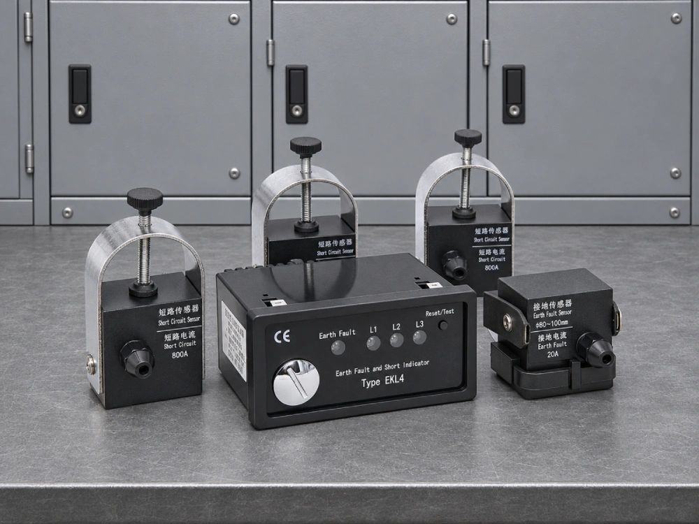
A cable type fault indicator operates by monitoring current changes through sensors installed around insulated cables. During normal operation, the device observes electrical signals within expected operating conditions. A short circuit typically produces a rapid current increase, while a ground fault may generate detectable residual current. The processing unit evaluates these signals against configured detection criteria. When the conditions indicate a fault, the device activates its indication mechanism. Some models also provide relay outputs for external monitoring systems. For example, the EKL4 Short-Circuit Grounding Fault Indicator for Cables supports adjustable fault-current thresholds, automatic reset, and alarm output.
Main Types and Indication Methods
Cable fault indicators can be classified according to their detection functions and indication methods. Short-circuit indicators monitor abnormal phase-current increases, while ground-fault indicators detect conditions associated with current flowing outside the intended circuit. Combined devices support both functions when properly configured. Fault information can be presented through several mechanisms:
- LED indication: Provides visible flashing signals after fault detection.
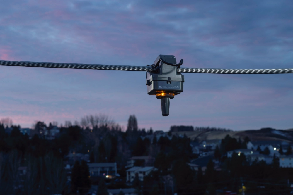
- Mechanical indication: Uses a flag or display mechanism to show fault status.
- Remote indication: Transmits alarm information to compatible monitoring equipment.
- Reset functions: Clear fault indications manually, automatically, or after a configured interval.
The available features depend on the specific device design and operating requirements.
Installation and Practical Considerations
Proper installation directly affects detection reliability. Cable-mounted sensors are typically positioned around insulated conductors, with the arrangement determined by the required fault detection method. Phase-current sensing and residual-current sensing may require different sensor configurations. Cable diameter, available installation space, and cable shielding arrangements must also be considered. Incorrect routing of shield grounding conductors through a zero-sequence sensor can affect residual-current measurements. Additionally, switching operations, load fluctuations, and unsuitable detection thresholds may produce misleading indications. Installation and commissioning should follow manufacturer specifications and appropriate electrical isolation procedures. Routine inspections should also verify sensor connections, indication functions, and power supply conditions.
Common Applications and Advantages
Cable fault indicators are widely used in medium-voltage distribution systems where rapid fault identification is important. Typical applications include underground cable networks, ring main units, cable branch boxes, and industrial distribution equipment. Their primary advantage is helping maintenance teams identify suspected faulted sections more efficiently. Clear indications can reduce unnecessary inspections and support faster restoration planning. For instance, the Cable Type Short Circuit Grounding Flash Fault Indicator provides visible fault information for cable and distribution network applications. These devices can also complement protection systems by supplying additional information during fault investigation.
Cable-Mounted vs. Panel-Mounted Fault Indicators
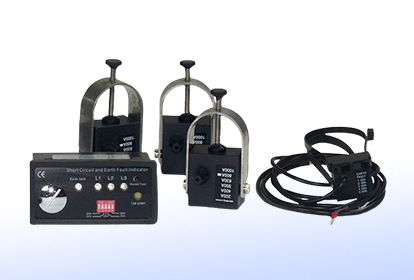
Cable-mounted and panel-mounted fault indicators differ mainly in their physical installation and display arrangements. Cable-mounted devices place sensing components around cables, while panel-mounted configurations provide accessible indication at the equipment front. Some systems combine cable-mounted sensors with separate panel-mounted displays. Their main differences are summarized below.
| Feature | Cable-Mounted | Panel-Mounted |
|---|---|---|
| Sensor Location | Around insulated cables | Integrated or remote sensors |
| Display Position | Near cable or separate unit | Cabinet front panel |
| Inspection | May require compartment access | Usually accessible from front |
| Applications | Cable branches and RMUs | Switchgear and control panels |
Frequently Asked Questions
Can a Cable Fault Indicator Detect Both Short Circuits and Ground Faults?
Yes, certain cable fault indicators can detect both short circuits and ground faults. However, not every model supports both functions. Short-circuit detection generally relies on abnormal increases in phase current, while ground-fault detection may use residual-current measurements. Combined indicators incorporate suitable sensing and processing functions for both conditions. Detection performance also depends on network grounding arrangements and configured thresholds. In some networks, ground-fault currents may be relatively low, requiring specialized detection methods. Before installation, engineers should confirm the device's supported fault types, operating characteristics, and compatibility with the intended distribution network.
Can a Cable Fault Indicator Be Installed Without Cutting the Cable?
Many cable-mounted fault indicators use clamp-on current sensors that can be installed without cutting the cable conductor. These sensors surround the insulated cable and detect electrical signals through magnetic coupling. This arrangement can simplify installation in suitable distribution equipment. However, installation requirements vary according to sensor construction, cable diameter, and available working space. Some configurations also require connections between sensors and external display units. Importantly, non-invasive installation does not automatically mean the equipment can be installed while energized. Qualified personnel must follow the manufacturer's instructions and applicable electrical safety procedures before beginning installation or maintenance work.
Can a Cable Fault Indicator Identify the Exact Fault Location?
A cable type fault indicator generally identifies whether a qualifying fault has passed through a monitored cable section. By comparing indications at multiple locations, maintenance personnel can narrow down the suspected faulted portion of a distribution feeder. However, the indicator usually cannot determine the exact physical distance to the fault or identify the precise location of damaged insulation. Accurate pinpointing may require specialized cable fault location equipment and additional diagnostic testing. Indicator results must also be interpreted alongside the network configuration and protection operation. Therefore, these devices support fault-section identification rather than replacing comprehensive cable fault testing methods.
Conclusion
A cable type fault indicator provides practical support for fault detection and troubleshooting in electrical distribution networks. By monitoring abnormal currents and displaying fault information, it helps maintenance teams identify affected cable sections more efficiently. Reliable operation requires appropriate sensor installation, suitable detection settings, and regular inspection. When integrated into distribution equipment, these devices can improve fault response and support more efficient network maintenance.