How Does A Circuit Lock Disconnect Switch Work?
A circuit lock disconnect switch ensures electrical isolation, lockout protection, and reliable equipment control for maintenance.
What Is a Circuit Lock Disconnect Switch?
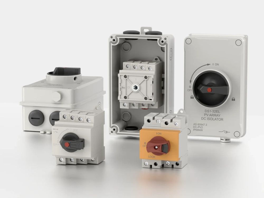
A circuit lock disconnect switch provides a controlled way to isolate electrical equipment from its power source. The device uses mechanical contacts to open the circuit and create separation between energized and de-energized sections. Its locking feature helps prevent accidental re-energization during service work. Unlike protective devices, its primary role centers on isolation and equipment shutdown. Operators can place the handle in an open position and secure it against unauthorized movement. Correct selection also requires attention to voltage, current, load type, poles, enclosure conditions, and installation requirements. Industrial equipment often combines a disconnecting device with upstream overcurrent protection. That arrangement gives the system both fault protection and a practical isolation point. Proper use therefore depends on the electrical design and established site safety procedures.
How Does a Circuit Lock Disconnect Switch Work?
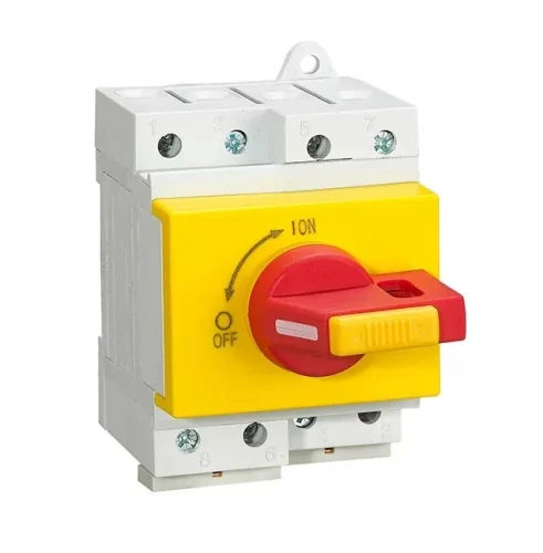
The operating mechanism converts handle movement into physical contact movement inside the enclosure. When the operator turns the handle, an internal linkage moves the main contacts apart. Opening these contacts interrupts the intended current path through the equipment. The mechanism also places the handle in a defined open position. A locking provision can then prevent movement toward the closed position. Some designs use direct handle mechanisms, while others use rotary or door-coupled arrangements. Each design must maintain reliable mechanical positioning during normal operation. Contact pressure also matters because closed contacts must carry current without excessive resistance. Internal components therefore require suitable insulation, mechanical strength, and thermal performance. The operating sequence should always match the equipment manufacturer's instructions and the site's electrical safety procedures.
How Does the Switching Mechanism Create Electrical Isolation?
Electrical isolation in a circuit lock disconnect switch depends on separating conductive parts by a suitable physical distance. Opening the contacts removes the normal conductive path between the supply and connected equipment. The switch design must maintain adequate insulation around energized components and terminals. Insulating barriers can also reduce the chance of accidental contact with live parts. Mechanical positioning provides another important layer of certainty during operation. A properly designed mechanism keeps the contacts stable after the operator reaches the open position. Some equipment also provides a visual indication that shows whether the mechanism sits in the open state. Workers should never rely on handle position alone when electrical safety requires voltage verification. Proper testing confirms the actual electrical condition before maintenance begins. These principles make physical separation a central part of reliable isolation practice.
Why Is the Locking Mechanism Important for Maintenance?
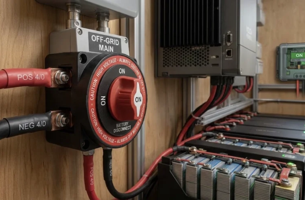
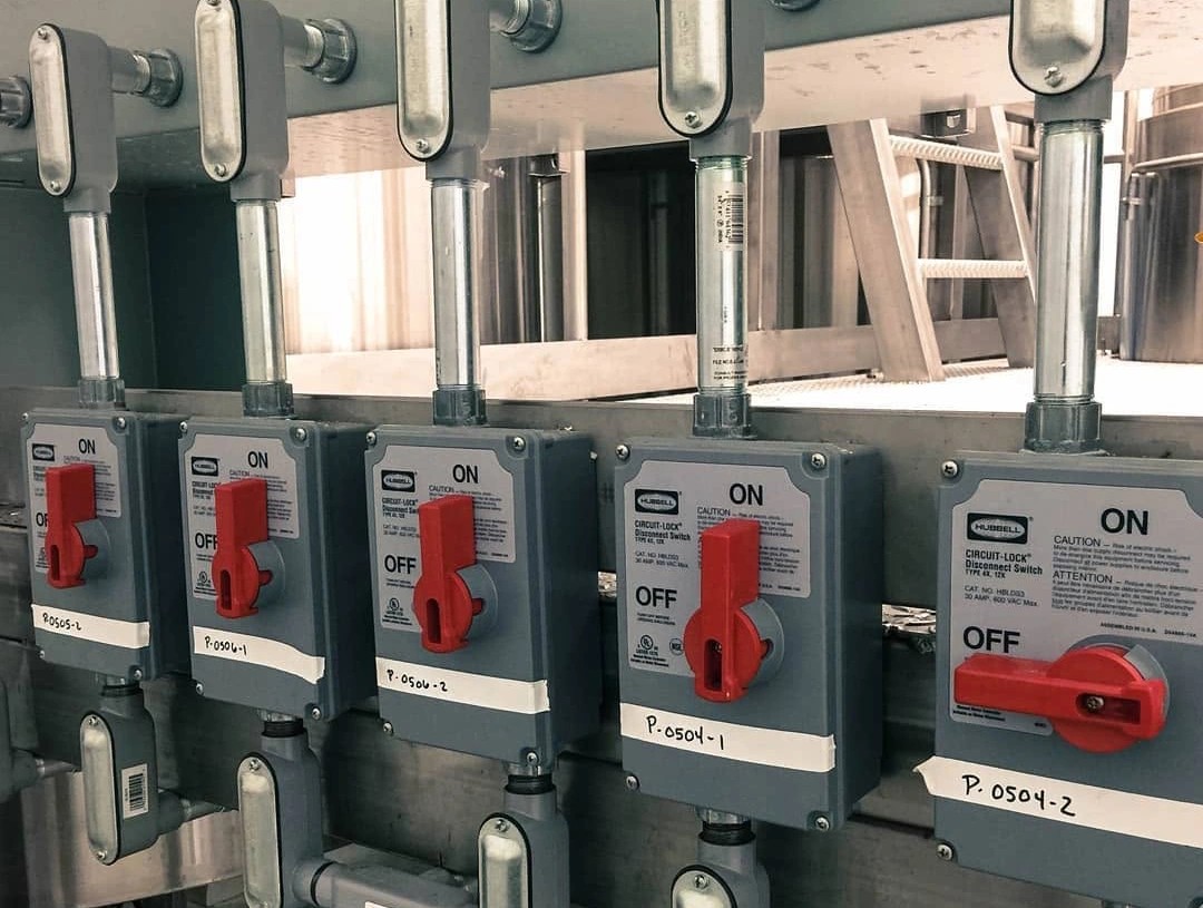
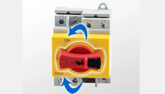
Maintenance work often requires workers to keep equipment disconnected for an extended period. A locking mechanism provides a physical method for restricting unauthorized operation during that period. The worker can place the handle in its open position before applying a personal lock. A suitable Disconnector Lock can help maintain that position against unintended movement. The exact locking arrangement depends on the equipment design and applicable workplace procedures. Some handles include dedicated holes that accept standard safety padlocks. Other designs use external locking accessories that secure the operating mechanism. Multiple-worker systems may require devices that accommodate several individual locks. Each person can then retain control over their own lock during shared maintenance. Locking alone does not prove that voltage is absent. Workers still need appropriate verification procedures before touching electrical conductors or components.
What Happens Inside the Switch During Operation?
Several internal components work together when an operator changes the switch position. Main contacts carry the circuit current while the equipment remains energized. Moving contacts travel away from stationary contacts when the operator opens the mechanism. Terminals connect incoming and outgoing conductors to the switching assembly. Insulating materials separate conductive parts and support electrical clearance requirements. Mechanical linkages transfer handle movement while maintaining a defined operating position. Some designs also include arc-control features for specific switching duties. Contact materials must tolerate repeated operation without excessive wear or unacceptable resistance. Thermal performance matters because electrical resistance can produce heat at high current levels. Mechanical wear can eventually affect contact alignment and operating force. Regular inspection should therefore consider both electrical connections and the physical condition of the operating mechanism.
Which Electrical Ratings Matter When Selecting a Disconnect Switch?
Electrical ratings determine whether the equipment can safely serve a particular installation. Voltage rating defines the electrical system range that the device can handle. Current rating indicates the continuous current that the switching path can carry under specified conditions. Load characteristics also influence the appropriate selection. Motors, transformers, heaters, and other loads can create different switching demands. AC and DC systems require careful consideration because their interruption characteristics differ. Pole configuration must match the conductors that require isolation. Short-circuit conditions also matter because the disconnecting device must work within the system's specified protection arrangement. Engineers should review the equipment rating together with upstream protective devices. Selecting only by nominal current can overlook important operating conditions. A complete evaluation should consider the electrical system, connected load, operating frequency, and expected switching duty.
| Rating Factor | What to Check | Why It Matters |
|---|---|---|
| Voltage | System voltage and device rating | Supports suitable insulation and switching performance |
| Current | Continuous equipment load | Helps prevent excessive heating during operation |
| Poles | Number of conductors requiring isolation | Ensures the intended circuit sections can be isolated |
| Load Type | Motor, heater, transformer, or other load | Determines suitable switching duty |
| Short-Circuit Conditions | Available fault current and protective coordination | Supports correct system-level protection |
What Do These Electrical Ratings Mean in Practice?
These ratings become meaningful only when they match actual operating conditions. For example, a motor circuit may experience starting currents above its normal running current. Transformer circuits can also create temporary inrush conditions when energized. Engineers should therefore compare equipment ratings with the connected load and switching requirements. Temperature can further influence the practical current capacity of electrical components. Conductors, terminals, and enclosure conditions can all affect heat dissipation. Installation location may also expose the equipment to dust, moisture, or corrosive substances. Those factors can influence insulation performance and mechanical reliability over time. A suitable rating provides a foundation, but correct installation remains equally important. The table above helps organize the principal electrical factors that affect selection. Reviewing them together reduces the risk of choosing a device based only on one numerical value.
What Is the Difference Between a Disconnect Switch and a Circuit Breaker?
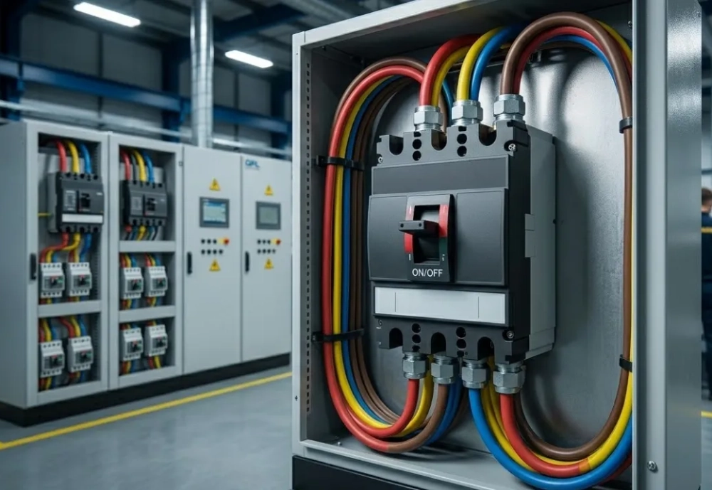
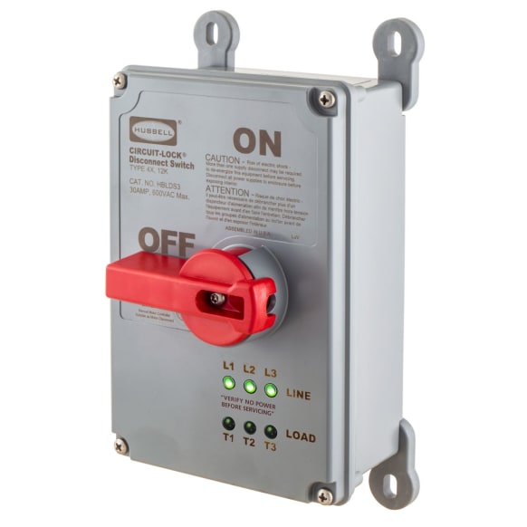
A disconnect switch and a circuit breaker perform different primary functions within an electrical system. A disconnecting device mainly provides a controlled isolation point for equipment and circuits. A circuit breaker primarily protects conductors and equipment against specified overcurrent conditions. Breakers can interrupt fault currents within their rated interrupting capacity. Disconnect switches may not provide equivalent overcurrent protection unless the specific design includes that function. Many installations therefore use both devices as parts of one coordinated system. The breaker handles protective interruption while the disconnect provides an accessible isolation point. Locking capability can add another layer of control during maintenance. Engineers should review the complete protection and isolation arrangement rather than selecting either device independently. The distinction becomes especially important when workers need a clearly controlled energy isolation point.
| Feature | Disconnect Switch | Circuit Breaker |
|---|---|---|
| Main Purpose | Equipment and circuit isolation | Overcurrent protection and interruption |
| Fault Protection | Depends on specific design | Core protective function |
| Locking | Common feature on suitable designs | Depends on breaker design and accessories |
| Maintenance Use | Provides an isolation point | Provides circuit interruption and protection |
| System Role | Isolation and controlled switching | Protection against specified electrical faults |
How Should a Lockable Disconnect Device Be Used During Maintenance?
Safe maintenance requires more than moving a handle into an open position. Workers should follow a defined procedure that identifies the correct energy source and equipment. A typical sequence includes the following actions:
- Identify the correct electrical supply and connected equipment.
- Shut down the equipment using the normal operating controls.
- Open the disconnecting device.
- Apply the assigned personal lock.
- Verify the absence of voltage using suitable test equipment.
- Complete the planned maintenance work.
- Remove the lock and restore power according to the approved procedure.
The sequence above emphasizes control of hazardous energy from identification through restoration. Workers should also consider stored electrical or mechanical energy where relevant. Verification requires suitable instruments and procedures for the voltage involved. Site rules may require additional steps, documentation, or authorized personnel. Equipment manuals can also specify operational limitations that affect safe switching. Following a consistent process reduces the chance of confusing a nearby circuit with the intended supply.
What Applications Use a Circuit Lock Disconnect Switch?
Industrial and commercial equipment often requires a dedicated point for electrical isolation. Manufacturing machinery commonly uses disconnecting devices near motors, control panels, and production equipment. HVAC installations can also require local isolation for compressors, fans, and associated controls. Distribution equipment may use similar devices where maintenance access requires controlled separation. Agricultural and utility applications can introduce additional environmental and mechanical demands. Outdoor equipment may require enclosures that resist moisture, dust, ultraviolet exposure, and temperature changes. Indoor industrial systems can face conductive dust, chemical vapors, or frequent cleaning processes. Application conditions therefore influence enclosure selection, terminal design, and operating mechanism durability. Maintenance frequency also matters because frequent switching can increase mechanical and contact wear. Engineers should match the device to both electrical requirements and the physical conditions surrounding the installation.
What Environmental Factors Affect Disconnect Switch Performance?
Environmental conditions can gradually influence the performance of a circuit lock disconnect switch. High humidity can encourage condensation when equipment temperatures fall below the surrounding air's dew point. Moisture can reduce insulation reliability and accelerate corrosion on exposed metallic components. Dust may accumulate around terminals and insulating surfaces, especially in industrial environments. Conductive contamination presents additional concerns because it can create unwanted current paths. Corrosive atmospheres can attack contacts, terminals, fasteners, and mechanical linkages over time. Outdoor installations may also experience temperature cycling that stresses materials and seals. An appropriate enclosure helps limit exposure, but enclosure selection must match the actual environment. Installation practices should also prevent water entry through cable openings and unused access points. Periodic inspection can identify corrosion, contamination, loose connections, or damaged seals before these conditions affect reliable operation.
How Can You Select the Right Circuit Lock Disconnect Switch?
Selection should begin with the electrical system rather than the enclosure dimensions alone. Determine the operating voltage and continuous load current first. Next, identify the connected load and its expected switching conditions. Confirm the required number of poles and the conductors that need isolation. Check available short-circuit current and the protective device coordination. Evaluate enclosure requirements based on indoor, outdoor, dusty, wet, or corrosive conditions. Installation space also matters because the operating handle needs sufficient access. Maintenance requirements can influence the preferred locking arrangement and handle configuration. Finally, verify applicable standards and manufacturer ratings for the intended application. The following table summarizes the main selection factors that should receive attention before purchase.
| Selection Factor | Key Question | Potential Issue if Ignored |
|---|---|---|
| System Voltage | Does the device rating match the supply? | Insulation or switching limitations |
| Load Current | Can the contacts carry the expected load? | Excessive heating and contact stress |
| Load Characteristics | What type of equipment will it control? | Unsuitable switching duty |
| Environment | What moisture, dust, or corrosion exists? | Accelerated deterioration |
| Locking Requirement | How will maintenance personnel secure isolation? | Reduced control during service work |
| Installation | Does the enclosure and handle fit the available space? | Difficult operation or poor accessibility |
What Installation Details Can Affect Disconnect Switch Reliability?
Installation quality can strongly influence long-term electrical performance. Conductors should match the terminals and the device's specified connection requirements. Loose terminals can increase contact resistance and create localized heating. Excessive tightening can also damage terminals, conductors, or threaded components. Installers should therefore follow the manufacturer's specified torque values. Cable routing should avoid unnecessary mechanical stress on terminals and operating components. The enclosure should provide adequate space for bending conductors without placing pressure on connections. Outdoor installations require careful attention to cable entries and sealing arrangements. Mechanical alignment also matters when the operating handle connects with an internal mechanism. After installation, qualified personnel should verify connections, operation, and required electrical tests. Proper installation preserves the intended relationship between electrical ratings, mechanical operation, and environmental protection.
What Safety Standards Should Be Considered?
Standards provide technical frameworks for a circuit lock disconnect switch, including electrical equipment design, installation, testing, and safe work practices. The applicable requirements depend on the installation location, equipment type, and governing jurisdiction. IEC standards commonly address low-voltage switchgear and controlgear requirements in international applications. UL standards may apply to equipment intended for markets using North American certification frameworks. NFPA 70 addresses electrical installation requirements in the United States, while NFPA 70E focuses on electrical safety in the workplace. These standards serve different purposes and should not be treated as interchangeable labels. Engineers should verify the exact standard edition and product category relevant to the project. Manufacturer documentation can identify ratings, installation limitations, and applicable certifications.
Local electrical codes may also introduce additional requirements. Compliance therefore requires reviewing the complete system rather than relying on one marking or specification.
FAQ
Can a disconnect switch replace a circuit breaker?
A disconnect switch normally should not replace a circuit breaker when overcurrent protection is required. The two devices serve different functions within an electrical system. A disconnecting device provides a controlled means of separating equipment from its electrical supply. A circuit breaker protects conductors and equipment against specified overcurrent conditions. Some specialized devices may combine switching and protective functions, but their ratings must support both duties. Engineers should review the manufacturer's specifications and the complete protection scheme. The required arrangement also depends on the installation code and equipment design. Using a disconnect without suitable upstream protection can leave a circuit inadequately protected. Therefore, selection should consider isolation, fault protection, load characteristics, and system coordination together.
Can a lockable disconnect switch be used for equipment maintenance?
A lockable disconnecting device can provide an important isolation point during equipment maintenance. Its locking mechanism can prevent another person from moving the operating handle unintentionally. However, the lock itself does not prove that the equipment has reached a zero-voltage condition. Workers should follow the site's established hazardous-energy procedure and verify the electrical state with suitable test equipment. The correct disconnect must also control the actual energy source serving the equipment. Stored electrical, pneumatic, hydraulic, or mechanical energy may require additional controls. Personal locks can provide individual control during shared maintenance activities. Procedures should also define who can apply and remove locks. Safe maintenance therefore combines physical isolation, personal control, verification, and documented work practices.
What should you check before selecting a disconnect switch?
Start by checking the system voltage and the equipment's continuous operating current. Next, identify the connected load because motors and transformers can create different switching demands. Confirm the required number of poles and the conductors that need isolation. Review available short-circuit current and the relationship between the disconnecting device and protective equipment. Environmental conditions also require attention, especially moisture, dust, corrosion, and outdoor exposure. Installation dimensions can affect enclosure selection and handle accessibility. Maintenance procedures may determine whether a specific locking arrangement is necessary. Finally, verify applicable standards, certifications, manufacturer ratings, and installation instructions. Considering these factors together creates a more reliable selection process than choosing a device based only on current rating.