How Does A Live-Line Ground Fault Indicator Detect Faults?
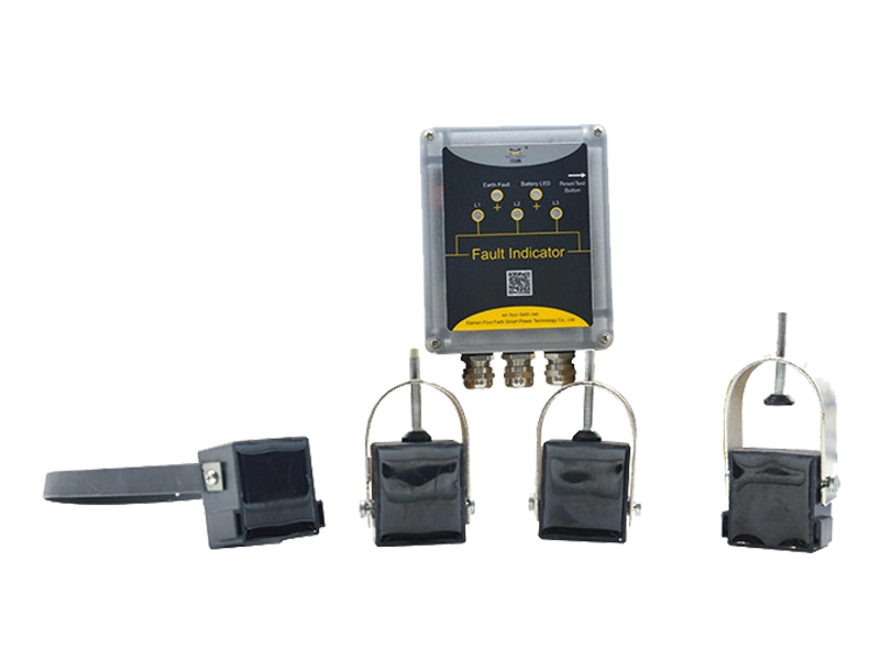
The live-line ground fault indicator fault detection system plays a critical role in modern power distribution networks. It identifies leakage currents and grounding anomalies while conductors remain energized. This capability improves operational safety and reduces outage risks in industrial environments. The system continuously monitors current flow in real time using magnetic sensing principles. It compares phase balance conditions to identify abnormal leakage paths. When irregular patterns appear, the device triggers visual or remote alerts. Engineers rely on this technology to maintain grid stability under high load conditions. It is commonly installed in substations, feeders, and distribution lines where continuous power supply is essential. Its rapid response capability helps prevent cascading failures across interconnected electrical systems.
Live-Line Ground Fault Indicator Fault Detection System Architecture and Core Design
The architecture of the live-line ground fault indicator fault detection system is built around layered sensing and signal conversion modules. Each layer processes electrical signals with increasing precision. The sensing unit captures current variations using split-core transformers. These transformers detect imbalance without interrupting live conductors. A conditioning circuit filters noise from transient spikes and harmonics. Processed signals are then forwarded to a microcontroller unit for evaluation. The controller determines whether deviations exceed safety thresholds. Output modules then activate alarms or communication signals. This modular structure ensures reliability in harsh electrical environments. Engineers design these systems for long-term field stability and minimal calibration requirements.
Live-Line Ground Fault Indicator Fault Detection Measurement Principles and Electrical Behavior
The measurement process in the live-line ground fault indicator fault detection system is based on zero-sequence current analysis. Under normal operation, phase currents remain balanced and sum to zero. When insulation failure occurs, leakage current flows toward the ground. This imbalance is detected through magnetic flux variation in sensing coils. The system converts this variation into electrical signals for processing. Digital filtering removes high-frequency noise caused by switching equipment. Threshold algorithms then evaluate whether the deviation indicates a fault condition. Sensitivity settings are adjustable based on grid requirements. This ensures adaptability across low-voltage and medium-voltage systems. Accurate measurement depends on stable sensor alignment and proper grounding configuration.
Core Components of Live-Line Ground Fault Indicator Fault Detection Systems
| Component | Function | Technical Feature |
|---|---|---|
| Current Sensor Coil | Detects imbalance in live conductors | High magnetic sensitivity core |
| Signal Processor Unit | Analyzes electrical variations | Microcontroller-based logic system |
| Alarm Module | Triggers fault indication | LED and remote communication output |
The table above outlines essential components used in detection systems. Each module performs a distinct function in ensuring system reliability. Sensor coils form the first detection layer and capture magnetic fluctuations. The processor unit evaluates signal integrity using embedded algorithms. Alarm modules provide immediate feedback for operators in control centers. Proper integration of these components ensures stable performance in fluctuating load conditions. Engineers often calibrate sensitivity levels based on grid topology. This configuration allows efficient fault identification even under partial load imbalance scenarios.
Signal Interpretation and Processing in Detection Systems
Signal interpretation in the live-line ground fault indicator fault detection process involves multi-stage filtering and decision logic. Raw sensor data often contains harmonic distortion and electromagnetic interference. The system first applies analog filtering to remove high-frequency noise. Digital processing then isolates meaningful signal patterns associated with ground faults. Decision algorithms compare real-time values with predefined thresholds. If deviation exceeds safe limits, the system classifies it as a potential fault event. Communication modules then transmit alerts to supervisory control systems. This layered processing approach improves accuracy and reduces false triggering rates. It also ensures consistent performance across varying environmental conditions such as humidity and temperature fluctuations.
Operational Features of Live-Line Ground Fault Indicator Fault Detection Systems
- Real-time current imbalance monitoring
- Adaptive sensitivity adjustment for grid conditions
- Remote alarm transmission capability
- High insulation resistance tolerance
- Low maintenance requirement in field deployment
The operational features listed above define system efficiency in practical applications. Real-time monitoring ensures immediate detection of abnormal electrical behavior. Adaptive sensitivity allows configuration across diverse voltage networks. Remote communication enhances response speed for maintenance teams. High insulation tolerance ensures stable operation in harsh environments. Reduced maintenance requirements lower long-term operational costs. These combined features make the system suitable for modern smart grid infrastructure. Engineers often prioritize these functions when designing large-scale distribution protection systems.
| Performance Parameter | Standard Range | Industrial Requirement |
|---|---|---|
| Detection Response Time | 10–50 ms | Sub-cycle fault identification |
| Operating Temperature | -25°C to 70°C | Outdoor electrical environments |
| Insulation Rating | ≥ 10 kV | Medium-voltage compliance |
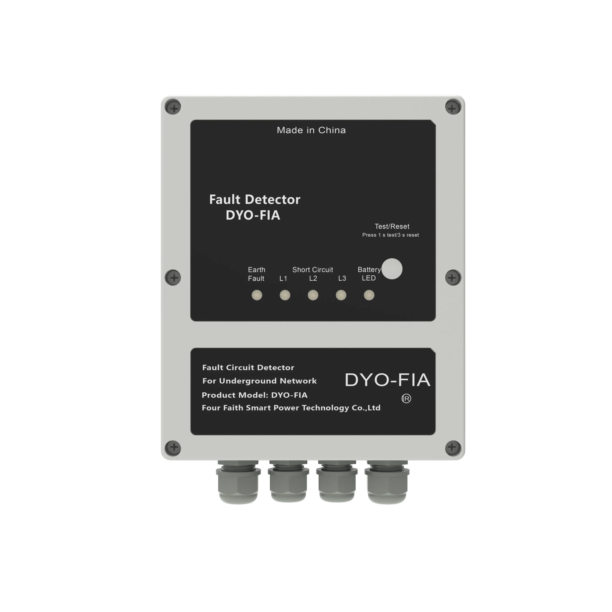
The performance table highlights key operational benchmarks for detection systems. Response time is critical for preventing fault escalation in distribution networks. Temperature tolerance ensures stable operation across seasonal variations. Insulation rating determines safety in high-voltage environments. These parameters are evaluated during system certification and field testing. Engineers use these values to verify compliance with industrial safety requirements. Proper adherence ensures reliable integration into national power infrastructure.
Installation Practices and System Deployment Considerations
Installation of detection systems requires careful alignment with conductor geometry and grounding layout. Technicians position sensors around insulated sections without interrupting live circuits. Mechanical stability is essential to avoid measurement drift. Cable shielding reduces electromagnetic interference from nearby equipment. Environmental sealing protects internal components from moisture and dust ingress. Calibration is performed after installation to ensure measurement accuracy. Proper spacing between conductors also improves detection sensitivity. Field engineers often conduct phased testing before full system activation. These practices ensure stable operation under continuous load conditions in industrial environments.
Live-Line Ground Fault Indicator Fault Detection Applications in Power Networks
The live-line ground fault indicator fault detection system is widely used in industrial substations and urban distribution grids. It supports continuous monitoring of feeder lines without requiring shutdown. Utility companies use it to reduce outage duration and improve service reliability. In industrial plants, it protects sensitive equipment from insulation failure damage. Renewable energy systems also integrate this technology to stabilize inverter-based networks. It enhances fault localization efficiency in complex grid structures. Maintenance teams rely on its rapid alerts to isolate affected segments quickly. This improves operational continuity and reduces financial losses associated with unexpected power interruptions.

Advanced Protection Strategies Using Detection Systems
The live-line ground fault indicator fault detection system enhances grid protection strategies through early anomaly detection. It identifies leakage currents before they escalate into major faults. Integration with SCADA systems allows centralized monitoring and control. Predictive maintenance models use collected data for failure trend analysis. Engineers optimize relay coordination based on detection feedback. This reduces unnecessary tripping in adjacent network segments. It also improves load distribution efficiency across substations. Combined with modern automation systems, it strengthens grid resilience against unpredictable electrical disturbances.
FAQ
What is the main function of a live-line ground fault indicator in fault detection?
A live-line ground fault indicator is designed to monitor electrical systems without interrupting power flow. Its primary function is to detect abnormal leakage currents that indicate insulation failure or grounding issues. The device continuously compares phase current balance in real time. When imbalance occurs, it triggers visual or remote alerts for operators. This allows maintenance teams to respond quickly before faults escalate. It is widely used in distribution networks where uninterrupted power supply is essential. The system improves safety by identifying hazardous conditions early. It also reduces downtime by enabling targeted maintenance instead of full system shutdown.
How does a live-line ground fault indicator detect faults in energized systems?
The detection process relies on electromagnetic sensing and zero-sequence current analysis. Under normal conditions, electrical currents remain balanced across phases. When a ground fault occurs, current leaks toward earth paths. The sensor coil detects this imbalance through changes in magnetic flux. The signal is then converted into electrical data for processing. Filtering circuits remove noise from external interference sources. The system evaluates processed signals using threshold-based logic. If deviation exceeds preset limits, a fault condition is confirmed. Alerts are then transmitted to control systems or displayed locally. This allows immediate identification of faulty sections in energized networks.