How Does A Remote Earth Fault Indicator Improve Safety?
Deploy a remote earth fault indicator to enhance grid safety, prevent outages, and protect medium voltage distribution equipment.

")
Enhancing Grid Security With A Remote Earth Fault Indicator
Modern medium voltage distribution networks require constant surveillance to maintain high operational reliability and safety. Unplanned outages often stem from insulation breakdown, causing hazardous ground faults that threaten nearby equipment. Power utility operators rely on advanced technology to quickly identify these dangerous electrical abnormalities. Implementing a remote earth fault indicator allows maintenance crews to pinpoint exact location problems immediately. This real-time visibility prevents extensive grid damage and ensures rapid service restoration for local communities. Reliable sensors detect minor current changes, sending alerts directly to centralized control centers via wireless communication. Consequently, field engineers skip manual line patrolling, which significantly reduces physical hazards during adverse weather. Efficient detection systems elevate safety levels by isolating faulty distribution lines before catastrophic equipment failures occur. These automated devices secure infrastructure and protect utility personnel working on energized electrical lines.
Core Sensing Technologies and Detection Mechanisms
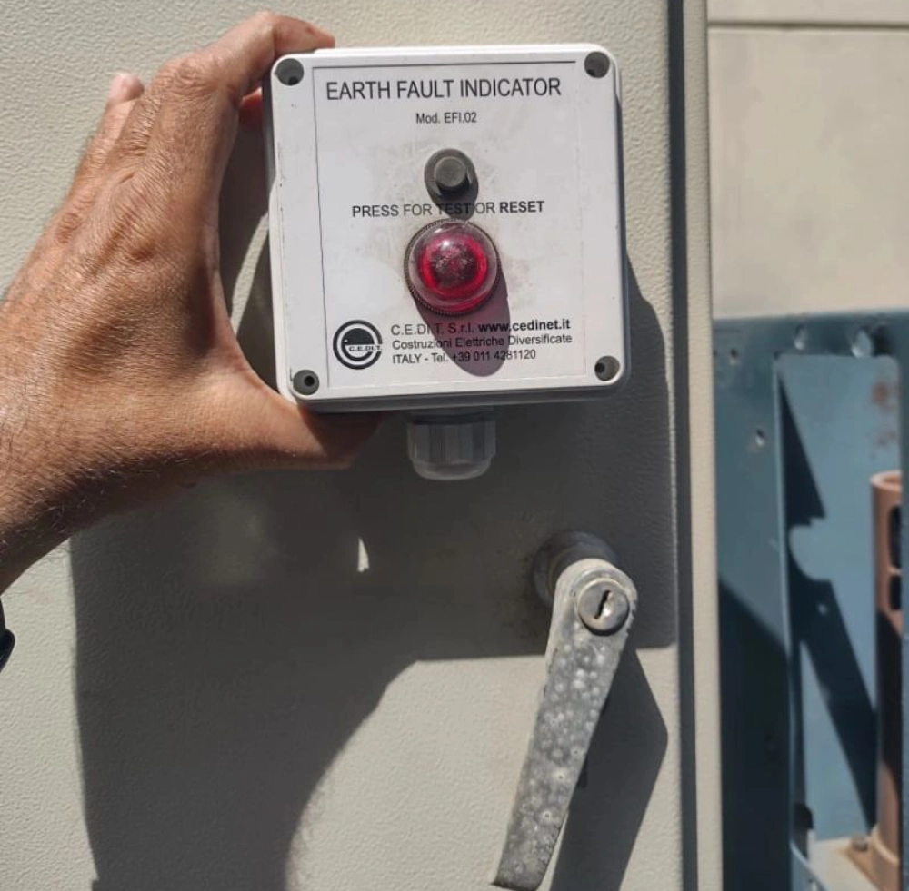
Modern monitoring systems utilize high-accuracy current transformers and voltage sensors to capture grid fluctuations. These specialized sensors measure electromagnetic fields surrounding overhead power lines or underground distribution cables. When a fault occurs, the sudden surge in current triggers the sensor's internal magnetic core. Advanced units, such as the Panel mounted Paddle Type Short circuit Fault Indicator, offer mechanical visual status displays. This physical paddle changes position immediately when fault currents exceed pre-set thresholds within the substation. Microcontrollers process these signals instantly, filtering out transient inrush currents caused by transformer energization. Safe grid operations depend on this precise filtering to avoid false trips during normal switching events. Integrated circuits then transmit the validated fault status to remote terminals for operator action. This combination of analog sensing and digital analysis guarantees extreme accuracy in highly volatile environments.
| Sensor Model Parameter | Specification Limits | Operational Standards |
|---|---|---|
| Current Detection Range | 5A to 1000A | IEC 61869-2 compliant |
| Response Time Threshold | Under 20 milliseconds | IEEE 386 standard |
| Communication Frequencies | LTE-M, NB-IoT, 868 MHz | CE and FCC certified |
Analyzing Technical Parameters of Earth Fault Sensors
Operators analyze key parameters from the specifications to choose the correct sensor for local substations. The current detection limits determine how effectively a remote earth fault indicator captures low-current ground faults. Fast response times ensure that the protection relay system isolates the compromised line segment immediately. Wireless communication frequencies allow seamless data transfer across vast distances directly to utility dispatch offices. These parameters guarantee compatibility with existing distribution network components and prevent physical equipment damage. Choosing certified models keeps utility operations compliant with strict international grid safety regulations worldwide. Field engineers review these specifications during initial system design to maximize overall system reliability. Robust hardware configurations withstand extreme environmental stresses while maintaining perfect monitoring accuracy throughout the year.
| Environmental Factor | Performance Range | Protection Mechanism |
|---|---|---|
| Operating Temperature | -40 to +85 degrees Celsius | Hermetically sealed housing |
| Ingress Protection Rating | IP67 or IP68 protection | Double O-ring silicon gaskets |
| Relative Humidity Resistance | Up to 100 percent condensing | Anti-condensation vent membrane |
Environmental Endurance of Sealed Fault Detectors
Outdoor electrical infrastructure must endure severe environmental conditions without experiencing component degradation or signal failures. Extreme temperatures require robust internal circuitry that maintains precise calibration across cold and hot seasons. High ingress protection ratings prevent moisture ingress, which causes catastrophic short circuits in sensitive equipment. Silicon gaskets keep rainwater out, maintaining a dry internal environment for critical telemetry components. Anti-condensation membranes allow pressure equalization, preventing internal moisture build-up during sudden temperature drops. These design features extend the lifespan of electronic parts installed in humid, coastal environments. Distribution networks benefit immensely when monitoring hardware remains functional during violent storms or floods. Reliable sealing prevents dirt contamination, ensuring that external indicators remain visible to utility field crews. Thus, robust environmental construction directly supports long-term grid stability and reduces operational maintenance costs.
- Verify that the conductor is completely de-energized before mounting the sensor unit.
- Clamp the core module securely onto the medium voltage cable using the insulated hot stick.
- Align the optical indicators outward so maintenance teams can view them from ground level.
- Connect the external wireless transceiver module to the local RTU interface panel.
Installation and Field Calibration of Ground Sensors
Field technicians must follow standardized safety protocols when deploying monitoring equipment on active distribution lines. Confirming de-energized status before mounting prevents arc flash incidents and protects workers from fatal shocks. Secure clamping of the sensor core guarantees accurate magnetic field measurement during normal operations. Proper alignment of the optical indicators allows quick visual checks from utility service trucks. This local display complements the remote earth fault indicator system by providing immediate on-site verification. Connecting the wireless module to local terminal units establishes a secure communication path to SCADA. Technicians verify signals during commissioning, confirming that the central office receives correct status telemetry. Regular testing schedules keep these field devices operating at peak performance levels throughout their lifespan.
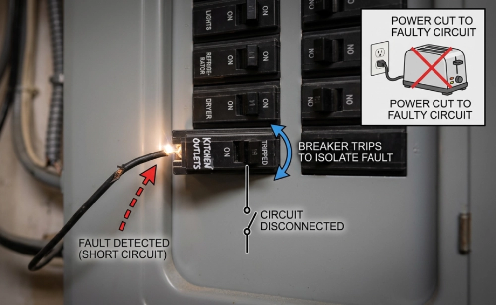
Why A Remote Earth Fault Indicator Minimizes System Downtime
Traditional outage management relies on manual visual inspections along miles of overhead distribution conductors. This slow, labor-intensive process increases downtime and prolongs dangerous power disruptions for consumers. Rapid identification of the faulted section changes this dynamic by directing crews straight to the problem. Automatic alerts provide immediate coordinates, saving precious hours during stormy nights when visibility is poor. Isolating damaged sections quickly allows operators to restore electricity to unaffected areas of the grid. Consequently, hospitals and factories experience fewer prolonged blackouts, boosting local economic stability and safety. Dispatchers coordinate maintenance trucks efficiently, reducing carbon footprints from unnecessary driving along rural roads. Customers appreciate the quick recovery times, which increases overall trust in public utility management. Investing in automation protects expensive substation assets from prolonged thermal stress during short-circuit events.
")
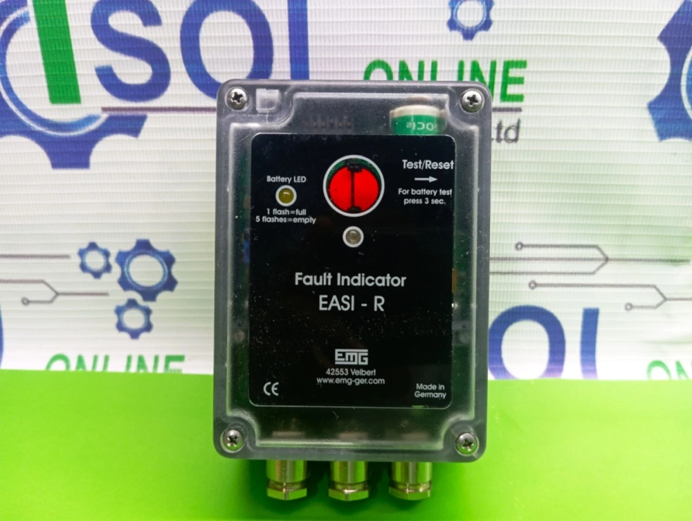
Power Supply Reliability and Battery Management
Field monitoring devices must operate continuously for years without requiring frequent, expensive battery replacements. Engineers design modern sensors with advanced low-power microcontrollers and lithium-thionyl chloride batteries. These high-capacity power cells function reliably under extreme heat and freezing winter temperatures. Smart power management units put the transmitter into deep sleep mode during normal grid operations. The sensor only wakes up to transmit data when it detects a sudden current anomaly. Some advanced models collect magnetic field energy from the conductor, charging the internal battery dynamically. This hybrid energy harvesting method extends the operational life of a remote earth fault indicator past ten years. Low-battery alerts inform control rooms ahead of time, allowing crews to plan replacements during routine inspections. Reliable power delivery ensures constant surveillance, protecting the grid from undetected electrical hazards.
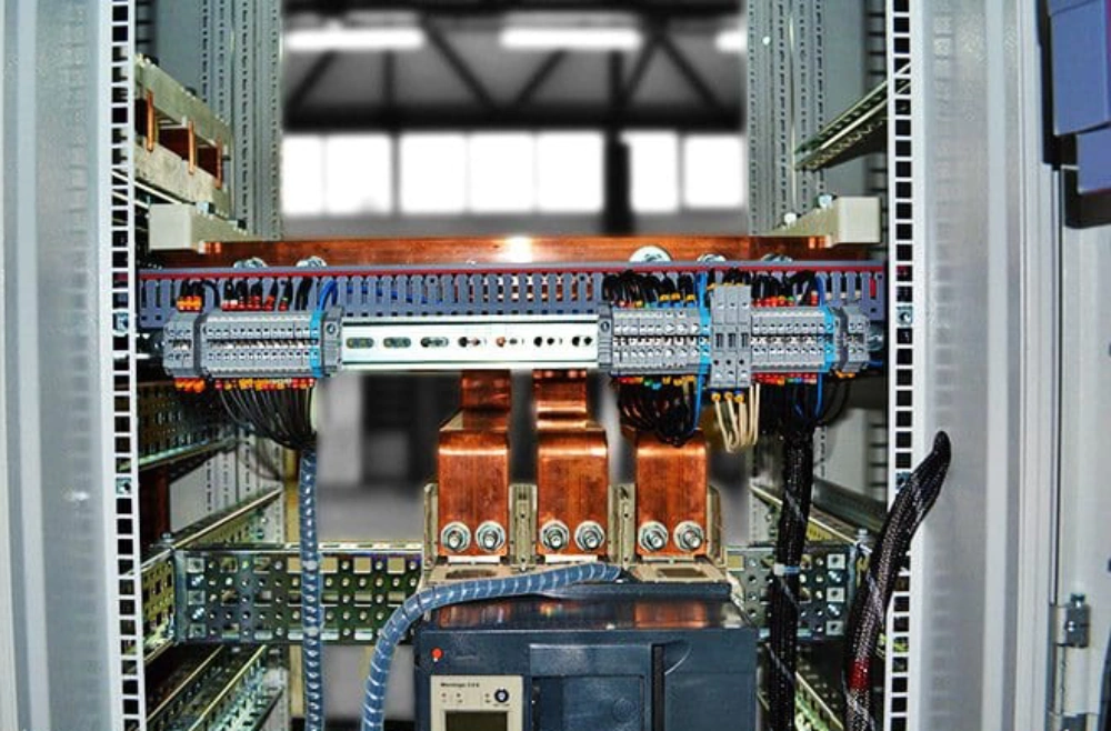
Integration with Distribution Automation and SCADA Systems
Modern grids rely on seamless integration between field sensors and centralized distribution management platforms. Standard communication protocols enable fault indicators to transmit data directly to utility control centers. Using tools like the Cable Type Short Circuit Grounding Flash Fault Indicator improves overall grid monitoring capabilities. This device sends real-time telemetry, allowing operators to spot localized grounding issues in underground networks. Advanced platforms map these alerts immediately, highlighting the specific substation or branch that requires attention. Automatic isolation loops open circuit breakers rapidly to prevent localized faults from spreading further. This coordinated defense system protects multi-million dollar assets and prevents extensive equipment fires. Grid operators gain complete operational control, drastically reducing hazardous manual field adjustments on high-voltage lines. Intelligent automation modernizes infrastructure and prepares power utilities for future electrical demands safely.

FAQ
How does a remote detection system handle low-current earth faults?
Advanced microprocessors analyze small zero-sequence current changes to detect subtle ground faults instantly. These units calculate phase current imbalances, comparing the values with predefined grid operating parameters. The remote earth fault indicator filters transient loads to prevent false alarms during normal operations. Digital algorithms identify the fault direction, ensuring that operators receive precise localization data quickly. Consequently, control rooms track physical fault paths without deploying ground crews for tedious manual lines patrolling.