How Does VPIS Improve Switchgear Safety And Monitoring?
Secure substation safety with a Switchgear Voltage Indicator Vpis. Prevent accidental contact through reliable voltage detection.
Ensuring Substation Safety with Visual Detection Systems
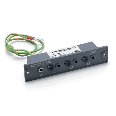
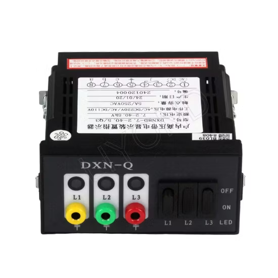
Electrical distribution networks require robust safety mechanisms to protect substation maintenance personnel from catastrophic hazards. Operators must verify that medium-voltage equipment remains fully de-energized before initiating any maintenance tasks. Accidents often happen when staff rely solely on operational logs rather than real-time physical confirmation. A certified Switchgear Voltage Indicator Vpis solves this problem by providing continuous, direct safety feedback. This compact device detects voltage directly from the primary circuit through reliable capacitive coupling technology. Engineers install these indicators directly onto the switchgear front panel for maximum visibility. Using reliable visual cues prevents fatal errors during routine lockout-tagout procedures. Ultimately, this safety tool ensures a secure working environment across industrial and utility power substations.
Operating Principles of a Voltage Presence Indicating System
Modern detection systems utilize capacitive coupling to measure electric fields within high-voltage enclosures safely. A high-voltage conductor connects directly to a coupling electrode embedded within the switchgear bushing. This configuration forms a capacitive voltage divider circuit that drops the primary voltage to safe levels. Low-energy signals travel through shielded coaxial cables directly to the front-panel display unit. The integrated Switchgear Voltage Indicator Vpis converts this small current into bright LED visual signals. These flashes immediately warn operators that the primary line remains fully energized. Liquid crystal displays or light-emitting diodes provide clear status indications even in dark substation basements. Because this process harvests energy from the electric field, it requires no external auxiliary power.
Compliance Requirements and IEC Standards for Substation Equipment
Utility grids globally require strict adherence to international safety standards for all medium-voltage installations. The prominent IEC 62271-206 standard defines the specific performance metrics for visual detection equipment. Manufacturers must rigorously test these electronic monitoring systems to guarantee reliable operation under severe industrial conditions. A compliant voltage presence indicator must activate clearly when the line voltage exceeds specific thresholds. These guidelines ensure that indicators never display false negatives during critical maintenance windows. Testing laboratories also evaluate environmental resistance, including dust penetration and humidity protection. Specifying certified equipment helps system integrators meet national grid code regulations effortlessly. Furthermore, fully compliant devices prevent heavy insurance liabilities and protect valuable substation infrastructure from unexpected damage.
Key Features of Modern VPIS Devices
Electrical designers distinguish between basic visual indicators and more sophisticated active diagnostic systems. Advanced installations utilize a modern Voltage Presence Indicating System with Diagnosis to track system health. This sophisticated equipment continuously monitors the connection cables between the coupling electrode and the display. If a wire breaks or a connection fails, the device immediately displays a clear fault signal. Such a safety feature eliminates the risk of an operator misinterpreting a broken indicator as a dead line. Rugged polycarbonate casings shield the display electronics from heavy physical impacts and chemical exposure. Integrated test sockets allow technicians to perform phase comparison measurements without opening any high-voltage doors. Selecting a Switchgear Voltage Indicator Vpis maximizes substation safety during complex routing and switching maneuvers.
| System Parameter | Standard Neon Indicator | Modern Solid-State System |
|---|---|---|
| Service Life Expectancy | Approximately 5 to 7 years | Exceeds 20 years of continuous use |
| Self-Diagnostic Capability | Not available | Continuous wire and signal monitoring |
| Auxiliary Power Requirement | Zero external power needed | Harvests energy from the line field |
Technical Analysis of Different Voltage Indication Technologies
The detailed comparison table above highlights the immense operational differences between traditional and modern monitoring methods. Older gas-discharge neon bulbs degrade rapidly over time and offer no internal diagnostics. In contrast, a modern Fixed Voltage Presence Indicating System provides decades of reliable operation. Solid-state LED technology maintains stable brightness and consumes minimal current from the coupling electrodes. These modern electronic circuits withstand high-voltage surges and harsh temperature fluctuations inside the switchgear. Technicians can rely on the consistent luminosity of solid-state indicators during critical isolation verification steps. Furthermore, the integration of continuous monitoring features prevents dangerous assumptions about circuit states. Specifying these rugged solid-state systems dramatically reduces maintenance overhead and increases substation uptime.
Benefits of a Switchgear Voltage Indicator Vpis
Implementing modern indicator technology offers critical advantages for safety and operational efficiency. First, it provides a completely passive monitoring solution that functions during main power outages. Second, operators can quickly identify phase mismatches by utilizing the integrated front panel sockets. This capability prevents catastrophic short circuits when connecting multiple medium-voltage feeders together. Additionally, the visual system eliminates the need for hot-stick testing on live busbars.
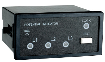
By keeping the cabinet doors closed, operators remain fully protected from devastating arc-flash hazards. Reduced exposure to live high-voltage components significantly lowers insurance premiums for industrial facilities. These immediate safety benefits make visual indication devices a standard specification for modern distribution networks.
| Electrical Parameter | Medium-Voltage Threshold | High-Voltage Threshold |
|---|---|---|
| Nominal System Voltage range | 3.6 kV to 40.5 kV | Exceeds 72.5 kV |
| Threshold Indicator Light-On | 10% of rated voltage | 10% of rated voltage |
| Threshold Indicator Light-Off | Less than 4% of rated voltage | Less than 4% of rated voltage |
Standards and Parameters for System Configuration
Configuring these monitoring systems requires precise alignment with the technical parameters outlined above. The activation thresholds prevent the display of misleading voltage signals during induction from adjacent cables. Engineers calibrate the coupling capacitance to match the nominal system voltage of each switchgear lineup. Properly calibrated Switchgear Voltage Indicator Vpis modules ensure that the indicators turn off below critical levels. This low threshold prevents static charges from lighting up the display when the busbar is dead. Additionally, the system remains highly responsive to genuine voltage presence down to ten percent of rated limits. Maintaining these tight tolerances protects technicians during hazardous grounding and maintenance procedures. Therefore, precise parameter matching remains a core requirement for successful substation safety engineering.
Critical Integration Requirements for High-Voltage Switchgear
Integrating a Switchgear Voltage Indicator Vpis into existing substation panels requires careful mechanical and electrical planning. Designers must position the display unit away from high-temperature components to protect sensitive electronics. Shielded coaxial cables must follow dedicated routing paths to avoid electromagnetic interference from power lines. Technicians must seal all external connection points against dust and moisture ingress to prevent corrosion. Standardized panel cutouts allow quick mounting and simplify the replacement of damaged indicator units. Moreover, installing reliable testing sockets ensures that operators can perform routine maintenance checks effortlessly. Robust grounding connections protect the low-voltage circuitry from transient overvoltages during lightning strikes. Following these manufacturing guidelines guarantees long-term operational reliability across municipal and industrial power grids.
- Gas-insulated switchgear (GIS) installations
- Air-insulated switchgear (AIS) panels
- Ring main units (RMU) in distribution networks
- Pad-mounted transformers and outdoor substations
- Industrial motor control centers (MCC)
Strategic Roles of Continuous Voltage Indicators
The application environments listed above demonstrate the versatility of these visual safety systems across modern networks. In compact ring main units, space constraints make physical contact testing extremely difficult and dangerous. Using integrated visual signaling devices provides operators with immediate safety data without requiring direct physical access. Similarly, gas-insulated switchgear benefits immensely from hermetically sealed coupling electrodes that resist environmental degradation. These robust devices withstand harsh outdoor climates in wind farm substations and heavy industrial environments. Reliable voltage indication prevents accidents during load-break operations in municipal utility grids. Ultimately, implementing these systems across diverse installations creates a unified safety culture for technical teams. Every single application scenario benefits from reduced operational risk and improved regulatory compliance.
Key Physical Specifications of a Switchgear Voltage Indicator Vpis
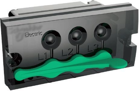
Selecting the appropriate visual presence indicator requires analyzing key physical and electrical characteristics carefully. Engineers look for wide operating temperature ranges, typically from minus twenty-five to plus eighty degrees Celsius. The enclosure protection rating must meet IP54 or higher to keep out dust and splashing water.