How Is A Switchgear Light Installed Inside A Cabinet?
Switchgear light installation covers mounting, wiring, switching, safety checks, and testing for reliable cabinet illumination.
Why Does Switchgear Light Installation Matter?
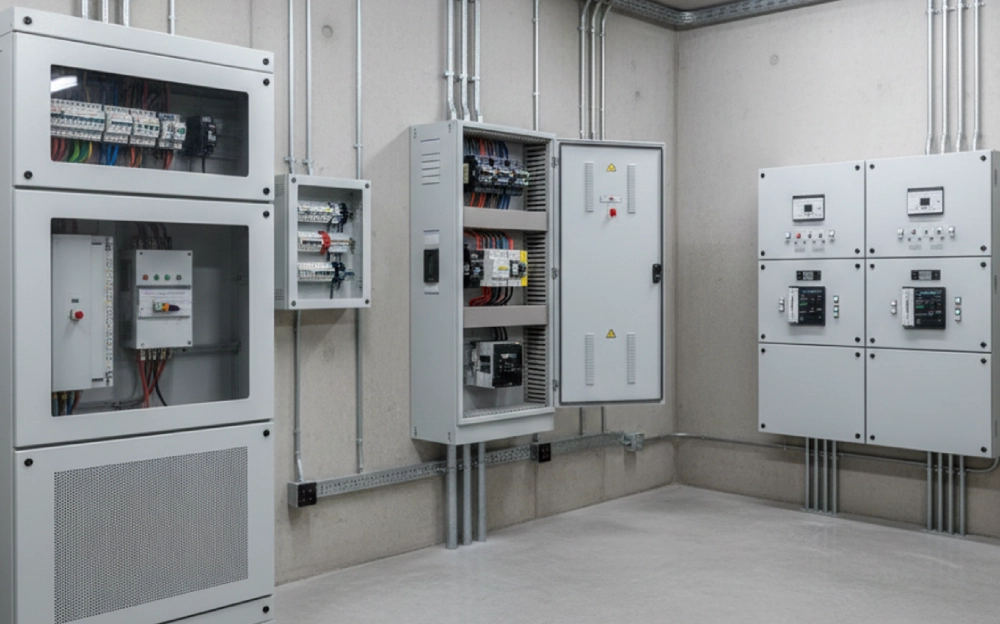
Switchgear light installation directly affects visibility during cabinet inspection, wiring, and maintenance. Internal lighting serves a different purpose from general room lighting. It must illuminate terminals, control components, labels, and operating mechanisms inside a confined enclosure. Poor positioning can leave important areas in shadow, even when the lamp produces enough light. A suitable fixture also needs compatible voltage, mounting hardware, wiring, and thermal characteristics. Engineers should therefore treat cabinet lighting as part of the enclosure design. The installation should not interfere with circuit breakers, busbar compartments, cable channels, or moving mechanisms. Proper planning also reduces unnecessary rewiring during commissioning. Field technicians can then inspect connections more efficiently and identify abnormal conditions more easily. This approach improves practical visibility without changing the primary electrical functions of the switchgear.
What Should Be Checked Before Installation?
Before installing an internal cabinet lamp, technicians should confirm the available auxiliary supply and cabinet layout. The first check should identify the voltage and whether the source provides AC or DC power. Next, installers should verify the fixture dimensions against the available mounting area. Cable entry points also require attention because crowded wiring channels can restrict installation space. Environmental conditions matter as well. Internal temperature, humidity, condensation, dust, and mechanical vibration can affect fixture reliability. The installer should also confirm whether the lamp needs a separate fuse or dedicated branch. Electrical work must follow the applicable local requirements and equipment instructions. Qualified personnel should isolate the relevant energy source before working on connections. Cabinet-light manuals commonly require secure mounting, free airflow, and electrical work by approved personnel.
Which Cabinet Areas Need The Most Light?
The best mounting position depends on the equipment arrangement rather than the geometric center of the cabinet. Installers should first identify areas that technicians inspect most frequently. These areas often include terminal blocks, protection devices, control wiring, auxiliary relays, and operating mechanisms. A lamp near the cabinet roof can provide broad coverage when the enclosure has an unobstructed interior. Side mounting can work better when tall components block downward illumination. Door-mounted lighting may provide useful coverage when technicians frequently inspect components near the front plane. However, door movement creates additional wiring requirements. Flexible conductors must tolerate repeated opening cycles without excessive bending. The fixture should also remain clear of hinges, handles, ventilation paths, and moving mechanisms. A practical layout therefore balances light distribution, mechanical clearance, cable routing, and maintenance access.
How Should The Mounting Position Be Selected?
Mounting position should follow the actual cabinet geometry and inspection workflow. A technician standing in front of an open enclosure needs light directed toward the working surface, not toward the rear of the door. Long linear fixtures often provide more even illumination across a wide panel area. Compact fixtures may suit narrow compartments with concentrated components. Installers should avoid locations directly behind large devices because those devices can create strong shadows. The lamp should also remain accessible for replacement or inspection. Screw-fixed mounting provides strong mechanical retention when vibration is a concern. Adhesive mounting may suit lighter fixtures and smooth surfaces, but surface preparation becomes important. Magnetic mounting can be convenient in temporary applications, yet permanent switchgear assemblies usually require a more secure arrangement. The mounting method should match vibration, service frequency, enclosure material, and expected equipment life.
What Electrical Connections Does The Lamp Need?
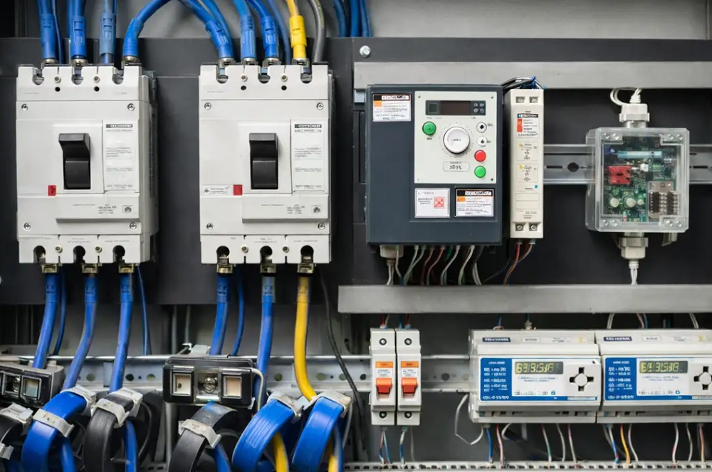
The electrical connection normally includes the auxiliary supply, protective device, control switch, and lighting fixture. The exact circuit depends on the cabinet design and available voltage. Some assemblies use a dedicated AC branch, while others use a DC auxiliary circuit. The lighting branch should remain electrically separated from critical control or safety functions where the design requires such separation. A local protective device can also prevent a lamp fault from affecting unrelated circuits. LED fixtures deserve particular attention because their electronic drivers can produce short-duration inrush currents during energization. Engineers should consider this behavior when selecting protective devices and switching components. Cable routing should keep conductors protected from sharp edges, excessive heat, and mechanical movement. Each termination should remain secure and identifiable. The final arrangement should also preserve access to existing terminals and secondary wiring.
What Electrical Data Should Be Confirmed Before Wiring?
| Parameter | What To Confirm | Why It Matters |
|---|---|---|
| Supply voltage | Rated AC or DC voltage | Prevents incompatible operation |
| Polarity | Positive and negative terminals for DC | Avoids incorrect connections |
| Power consumption | Fixture wattage or current | Supports circuit sizing |
| Control method | Manual or door-operated switching | Matches maintenance workflow |
| Mounting method | Screw, clip, or approved attachment | Determines mechanical stability |
| Wire routing | Entry path and flexible sections | Prevents cable interference |
| Thermal conditions | Expected cabinet temperature | Protects long-term performance |
| Protection | Required fuse or circuit protection | Limits fault impact |
These parameters should be confirmed before any conductor reaches the fixture. A simple data check prevents many installation problems because electrical and mechanical requirements often interact. For example, a higher-power fixture may require different branch protection or a larger supply margin. A door-operated arrangement also needs enough flexible cable length for repeated movement. The installer should verify the final cable path with the cabinet door fully open and fully closed. Terminal identification should remain clear after all conductors are installed. The fixture should never depend on an improvised connection that makes future maintenance difficult. Documentation should record the supply source, rated voltage, control method, and fixture location. This information gives maintenance personnel a clear reference during future inspection.
How Should The Light Be Controlled?
Door-operated switching is common because the lamp can illuminate the cabinet when access begins. Manual switching can also work when operators need independent control over the lighting circuit. The choice depends on cabinet access frequency, maintenance procedures, and the available auxiliary circuit. A door switch should not obstruct the gasket or prevent proper door closure. Its operating position must remain stable after repeated opening cycles. Manual switches should remain easy to reach without requiring contact with exposed energized components. The control circuit should also avoid unnecessary interaction with safety-related functions. A real switchgear light installation example shows why this matters. Public electrical specifications have used LED cabinet lights with door-switch control and top-of-cabinet mounting, showing that this arrangement can suit practical enclosure designs. The final control method should therefore follow the cabinet's mechanical and electrical architecture.
What Does A Typical Installation Sequence Look Like?
A practical installation can follow this sequence:
- Isolate the relevant electrical supply before starting work.
- Confirm the lamp rating and auxiliary voltage.
- Mark the mounting position inside the cabinet.
- Check clearance from devices, wiring, and moving parts.
- Secure the fixture using the approved mounting method.
- Route and protect the lighting conductors.
- Connect the control device and protective circuit.
- Inspect every termination before energizing.
- Test illumination and switching operation.
- Record the final circuit and mounting details.
This sequence creates a controlled path from mechanical installation to electrical commissioning. Each stage should be completed before the next stage begins. Installers should avoid routing cables before confirming the final fixture position. Otherwise, later repositioning can create unnecessary bends or cable extensions. The cabinet door should also move through its complete travel after wiring. This check can reveal cable tension that remains hidden when the door stays closed. Final inspection should confirm that no conductor touches sharp sheet-metal edges. Any unused openings should receive suitable protection according to the enclosure design. The completed installation should leave enough service space for future maintenance. A disciplined sequence reduces rework and helps keep the lighting system separate from unrelated cabinet functions.
How Should A Switchgear Light Installation Be Tested?
After wiring, switchgear light installation should be tested under conditions that represent normal cabinet access. First, technicians should verify the supply voltage at the intended connection point. They should then check polarity when the fixture uses DC power. The lamp should operate consistently through its complete switching cycle. Door-operated systems need testing with the door opened and closed repeatedly. The installer should also inspect illumination across terminals, labels, cable channels, and operating mechanisms. Any strong shadow should trigger a mounting-position review. Thermal behavior deserves attention during an extended operating test. LED equipment can generate switching transients, so the protective and switching components should match the actual load. Finally, technicians should inspect mechanical retention and cable movement. Testing should confirm both electrical operation and practical visibility rather than merely proving that the lamp turns on.
What Should Be Checked During Final Inspection?
| Inspection Item | Acceptance Focus | Typical Action |
|---|---|---|
| Mechanical fixing | Fixture remains stable | Tighten or correct mounting |
| Electrical supply | Correct rated voltage | Verify with approved meter |
| Wiring | Secure and protected | Rework loose or exposed conductors |
| Switching | Reliable operation | Adjust switch position |
| Door movement | No cable tension | Reroute flexible wiring |
| Illumination | Key areas remain visible | Reposition fixture if needed |
| Thermal condition | No abnormal heating | Check load and ventilation |
| Component clearance | No interference | Adjust mounting location |
| Documentation | Circuit details are recorded | Update cabinet records |
Final inspection should consider the complete cabinet rather than the lamp alone. A fixture can operate electrically while still creating a maintenance problem. For example, a cable may become stretched when the door reaches its maximum opening angle. Another issue may appear when the light creates glare on identification labels. Technicians should therefore evaluate the installation from the same position used during actual service work. The inspection should also confirm that the lamp does not block ventilation or contact heat-producing equipment. Product instructions should remain available for future maintenance. A cabinet-light specification can also define requirements for secure mounting, dry conditions, and unobstructed airflow. These checks create a more reliable installation record.
What Does A Real Cabinet Lighting Installation Look Like?
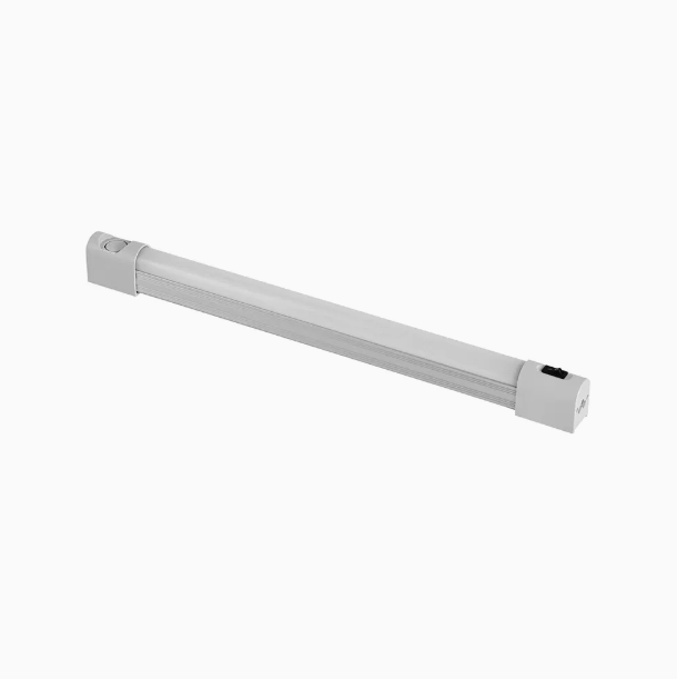
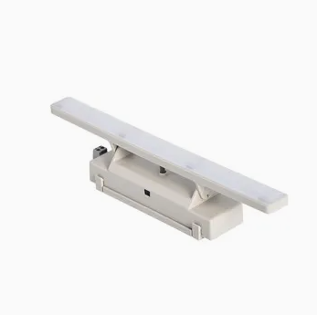
Consider a low-voltage distribution cabinet used for routine electrical maintenance. Technicians initially found the terminal area difficult to inspect because the cabinet door and upper devices created shadows. The engineering team selected a linear LED fixture and positioned it near the upper interior area. The mounting location avoided the circuit breaker handles and cable entry paths. The lighting circuit used the cabinet's approved auxiliary supply and a dedicated control arrangement. The team then opened the door fully and checked cable movement before final tightening. After energization, technicians inspected terminal labels, control wiring, and device status indicators from the normal working position. The final test showed better visibility across the service area without changing the primary equipment layout. A similar approach can use a CM-L2 Cabinet LED Light for Switchgear when its electrical and mechanical specifications match the enclosure requirements.
How Can The Installation Avoid Common Problems?
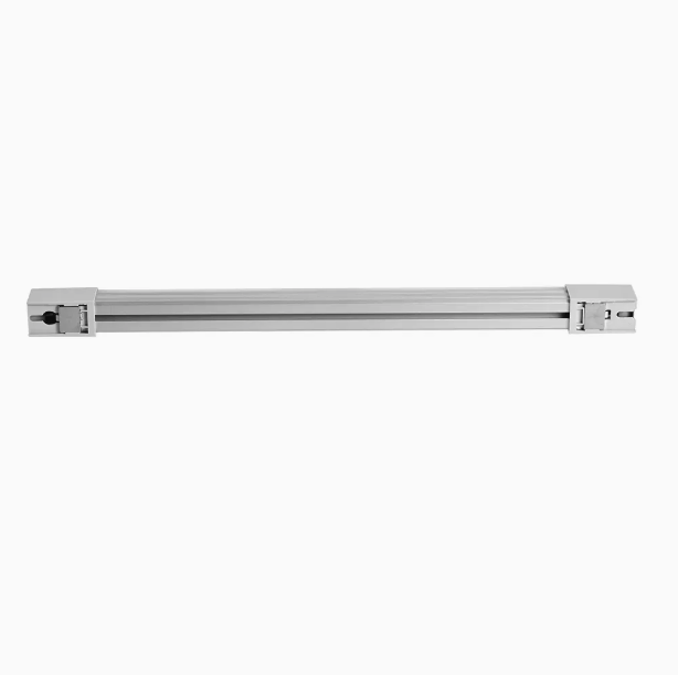
Several recurring problems reduce cabinet lighting performance even when the selected lamp is suitable. The most common issue is placing the fixture where large components block the working area. Another problem occurs when installers select a power source without checking its voltage or available capacity. Loose terminals can create intermittent operation and increase troubleshooting time. Poor cable routing may also cause fatigue near a moving cabinet door. Heat accumulation can become another concern when a fixture blocks ventilation openings. Installers should avoid assuming that a lamp's brightness alone determines its usefulness. Beam direction, mounting height, component density, and surface reflectivity all affect practical visibility. The fixture should also remain serviceable after other equipment is installed. For smaller or differently arranged enclosures, a CM-1 Cabinet Light for Switchgear may provide another suitable configuration when its specifications match the application.
How Can Maintenance Teams Improve Long-Term Reliability?
Long-term reliability depends on more than the initial electrical connection. Maintenance teams should periodically inspect mounting points, terminals, cable insulation, and switching components. Door-operated systems deserve special attention because repeated movement can stress flexible conductors. Dust accumulation can also reduce optical output and affect heat dissipation. Technicians should clean the fixture according to its manufacturer's maintenance instructions and avoid damaging the optical surface. Any flickering, unusual heating, discoloration, or abnormal noise should trigger further inspection. Cabinet lighting should never be treated as an isolated accessory when it shares an auxiliary supply with other equipment. A lighting fault should remain localized whenever the cabinet design permits separate protection. Clear circuit identification also helps future technicians locate the correct supply quickly. These practices make maintenance more predictable and reduce unnecessary downtime during inspection work.
What Should Buyers Confirm Before Ordering Cabinet Lighting?
Procurement teams should evaluate the lamp against the cabinet rather than selecting by wattage alone. The first requirement is the correct auxiliary voltage and current type. Next, buyers should compare fixture dimensions with the planned mounting surface. Optical output, beam distribution, and color characteristics should match the inspection task. Mechanical retention should suit vibration and expected maintenance frequency. Environmental ratings should also match temperature, humidity, dust, and condensation conditions. Wiring terminals must accommodate the intended conductor size and connection method. Control compatibility matters when the cabinet uses door-operated switching. Buyers should also request technical drawings when mounting space is limited. A pre-production sample can reveal clearance or glare problems before bulk assembly begins. Installation instructions should identify mounting limits, electrical ratings, and maintenance requirements. This procurement process reduces redesign work and improves consistency across repeated cabinet builds.
FAQ
Can A Switchgear Light Be Installed In Any Cabinet Position?
Not every cabinet position provides suitable illumination or mechanical clearance. The fixture should illuminate the main inspection areas without blocking equipment, ventilation paths, or moving mechanisms. Installers should also consider cable routing and door movement. A top-mounted fixture may provide broad coverage in an open enclosure. Side mounting may work better when tall devices create shadows. Door mounting can improve front-area illumination but requires flexible wiring. The mounting surface must also support the fixture securely during normal cabinet operation. Electrical clearance and applicable enclosure requirements remain important throughout the process. The final position should therefore come from the cabinet layout and maintenance workflow. A lamp that fits physically may still perform poorly if its light is blocked by equipment.
Should A Switchgear Light Use A Door Switch?
A door switch can provide convenient automatic illumination when technicians open the cabinet. It reduces the chance of leaving the lamp energized after maintenance. However, the decision depends on the cabinet design and control requirements. The switch must not interfere with the door gasket, hinge, or locking mechanism. Its wiring also needs enough flexibility for repeated door movement. Manual switching can remain practical when operators require independent lighting control. Both methods should use components compatible with the lamp's electrical characteristics. LED fixtures may produce short switching transients, so the control circuit should suit the actual load. The selected method should also avoid affecting safety-related circuits. For frequently serviced cabinets, door-controlled lighting can provide a practical balance between visibility, convenience, and operating discipline.
What Should Be Tested After Switchgear Light Installation?
Testing should cover electrical operation, mechanical security, switching behavior, and actual illumination. Technicians should first verify the supply voltage and connection polarity where applicable. Next, they should confirm that the fixture operates reliably through repeated switching cycles. Door-controlled systems require several complete door movements during testing. The installer should inspect the cable for tension, sharp bends, or interference with hinges. Illumination should be checked around terminals, labels, devices, and other service points. Any major shadow should prompt a review of the mounting position. The fixture should also operate without abnormal heating, flickering, noise, or visible damage. Final checks should confirm that the lamp does not obstruct ventilation or cabinet mechanisms. Test results and circuit details should then be recorded for future maintenance. This creates a traceable installation record for later inspections.