How Should A Switchgear Light Be Wired In A Cabinet?
Switchgear light wiring covers power supply, circuit protection, door switching, conductor routing, testing, and reliable cabinet lighting.
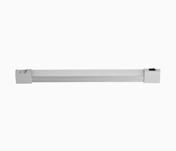
A switchgear light wiring system provides controlled illumination inside an electrical cabinet. It helps technicians inspect terminals, devices, labels, and wiring during service work. The lighting circuit normally connects to an auxiliary power source rather than the main power path. Its design should match the cabinet voltage, protection scheme, and operating environment. Proper routing also prevents contact with moving mechanisms and high-temperature components. Door-operated switching can turn the lamp on when personnel open the cabinet. Manual switching can provide independent control when required by maintenance procedures. Reliable terminals and protected conductors also reduce intermittent lighting faults. Therefore, cabinet lighting requires more than simply connecting a lamp to an available supply. The complete circuit should support safe access, clear visibility, straightforward maintenance, and dependable operation throughout the cabinet service life.
What Does Switchgear Light Wiring Need to Achieve?
The lighting circuit should provide sufficient illumination without affecting essential switchgear functions. A cabinet contains many components within a limited space. These components can include circuit breakers, contactors, protection relays, terminal blocks, control transformers, and auxiliary devices. Technicians need clear visibility when checking these components during commissioning or maintenance. The lamp should therefore illuminate the working area rather than create strong glare toward the operator. Its mounting position should also avoid interference with moving mechanisms and removable components. Good switchgear light wiring keeps the lighting circuit electrically independent from critical control functions where practical. This separation limits the effect of a lighting fault on other auxiliary equipment. It also makes troubleshooting easier because technicians can isolate the lighting branch without disturbing unrelated circuits.
Which Power Supply Is Suitable for a Cabinet Light?
Cabinet lights can operate from several auxiliary supply voltages. Common choices include 24 VDC, 110 VDC, 220 VDC, and 220–240 VAC. The correct choice depends on the cabinet control architecture and available auxiliary supply. A 24 VDC system can simplify low-voltage control arrangements in many industrial panels. Higher DC voltages may appear in protection and substation control systems. AC supplies can also serve cabinet lighting when the panel design provides a suitable auxiliary circuit. The lamp voltage must always match the actual supply specification. Designers should also check voltage tolerance, frequency requirements, power consumption, and inrush characteristics. A mismatch can cause overheating, flickering, premature failure, or complete loss of illumination. The selected supply should therefore come from the cabinet electrical design rather than from the main bus voltage.
How Should the Light Circuit Be Separated From Main Equipment?
Cabinet lighting normally belongs to the auxiliary electrical system. The lighting branch should not become an uncontrolled extension of the main power circuit. A separate branch makes isolation and maintenance more convenient. It can also prevent a lighting fault from unnecessarily affecting protection or control equipment. The circuit can receive power through an auxiliary distribution point, terminal block, or dedicated protective device. Designers should identify the lighting branch clearly on the electrical schematic. Physical separation can also improve maintenance safety when multiple voltage levels exist inside one cabinet. Control wiring, power wiring, and lighting conductors should follow the cabinet wiring rules used by the manufacturer. The actual arrangement depends on the switchgear construction and applicable project standards. Clear circuit identification also helps technicians locate the correct isolation point before replacing a damaged lamp or switch.
What Protection Should the Cabinet Light Circuit Have?
A cabinet light should have protection appropriate to its supply and conductor size. Small lighting loads still require protection against short circuits and abnormal current. A miniature circuit breaker or fuse can protect the branch when its characteristics match the circuit design. The protective device should not simply use the largest available rating. Its rating should consider conductor capacity, expected load, fault conditions, and coordination with upstream protection. A dedicated protective device can also simplify fault isolation during maintenance. The table below shows typical design considerations rather than fixed installation values.
| Design Item | Typical Consideration | Purpose |
|---|---|---|
| Supply voltage | Match the cabinet auxiliary circuit | Prevent incorrect lamp operation |
| Branch protection | Fuse or circuit breaker | Limit fault current |
| Conductor size | Match load and protection | Prevent excessive conductor heating |
| Isolation | Provide accessible disconnection | Support safe maintenance |
| Identification | Use clear circuit labels | Speed up fault tracing |
The protection arrangement should remain consistent with the cabinet schematic. Technicians can then identify the lighting branch without tracing unrelated conductors. A properly selected protective device also reduces unnecessary shutdowns when a lamp or terminal develops a fault. Designers should verify coordination with the upstream auxiliary supply. This check becomes especially important when several cabinets share one auxiliary distribution system. Overly sensitive protection may cause nuisance trips during switching or startup. Excessive protection may leave conductors inadequately protected during a short circuit. The physical location matters as well. Protection should remain accessible while avoiding accidental contact with energized parts. Clear labeling should identify the device and its associated lighting branch. These details make maintenance faster and reduce the chance of isolating the wrong circuit.
How Should Door Switching Work With Switchgear Light Wiring?
Door-operated lighting provides automatic illumination when cabinet access begins. A door switch can control the lamp through a suitable auxiliary contact arrangement. When the door opens, the contact changes state and energizes the lighting circuit. When the door closes, the lamp turns off and reduces unnecessary operating time. This arrangement works well for cabinets that receive frequent inspection. The switch position should allow reliable mechanical operation throughout repeated door cycles. It should not obstruct the gasket, latch, hinge, or door frame. The wiring also needs enough flexibility where conductors cross between fixed and moving structures.
A manually operated switch can provide an alternative when maintenance personnel need independent lighting control. Some cabinets may use both functions, depending on the operating philosophy. The selected method should match actual access procedures rather than follow a generic layout.
What Wiring Route Keeps the Cabinet Light Reliable?
Reliable routing requires attention to mechanical movement, heat, and electrical interference. Lighting conductors should remain away from sharp edges and moving assemblies. Breaker operating mechanisms can create repeated movement during normal operation and maintenance. A poorly routed conductor may rub against metal surfaces or become trapped during component movement. Door-mounted lights require additional attention because the door repeatedly changes position. Flexible wiring should maintain a suitable bending path without excessive tension. Conductors should also remain separated from high-temperature components where possible. Strong power conductors can produce electromagnetic fields that may affect sensitive control circuits. Proper routing reduces unnecessary interaction between these systems.
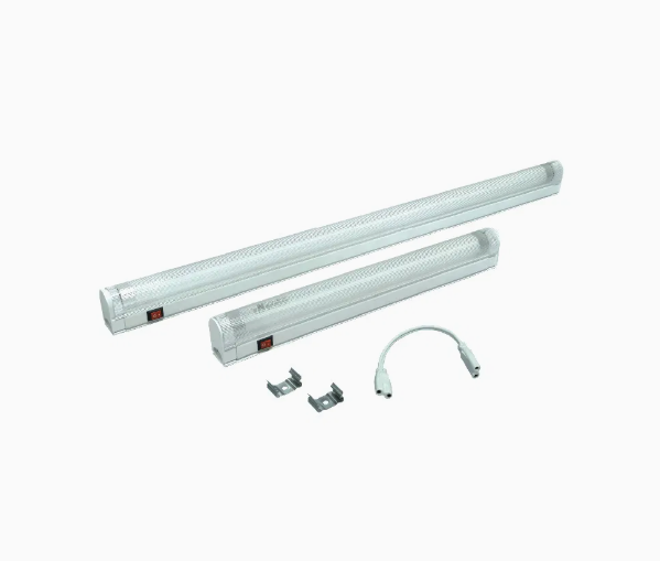
The following points help establish a practical cabinet lighting route:
- Keep conductors away from moving mechanical assemblies.
- Protect wires near metal edges and entry points.
- Maintain suitable bending space near cabinet doors.
- Avoid unnecessary parallel routing beside high-power conductors.
- Secure loose wiring with appropriate cabinet wiring accessories.
- Leave sufficient service length for component replacement.
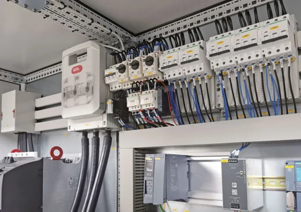
After routing is complete, technicians should inspect the entire conductor path manually. The wire should remain stable when the cabinet door moves through its full travel. No conductor should become stretched, pinched, or exposed to an abrasion point. Cable supports should hold the wiring without damaging insulation. The route should also allow technicians to remove the lamp or switch without dismantling unrelated circuits. This maintenance access becomes valuable in cabinets with dense internal layouts. A clean route improves both reliability and fault tracing. It also reduces the possibility of accidental damage during later modifications. The final arrangement should match the approved electrical drawing and cabinet assembly requirements. Any field change should receive proper documentation before the equipment returns to service.
Which Terminals and Conductors Should Be Used?
The conductor size should correspond to the lighting load and protective device. Even low-power LED lamps require mechanically secure connections. Loose terminals can create resistance, localized heating, intermittent operation, and eventual circuit failure. Terminal blocks should suit the conductor type and connection method. Crimped ferrules can improve conductor retention in compatible terminal systems. Each wire should also receive a clear identification number where the project documentation requires it. The table below summarizes common wiring elements and their functions.
| Wiring Element | Primary Function | Important Check |
|---|---|---|
| Supply conductor | Feeds the cabinet lamp | Correct voltage and insulation |
| Neutral or return conductor | Completes the circuit | Secure termination |
| Protective conductor | Supports protective bonding | Correct continuity |
| Door switch conductor | Controls automatic operation | Correct contact sequence |
| Terminal block | Provides organized connections | Torque and identification |
| Wire marker | Supports circuit tracing | Matches electrical drawings |
Terminal quality becomes particularly important during long service periods. Cabinets can experience vibration, thermal cycling, and repeated maintenance activity. These conditions can gradually affect poorly secured connections. Technicians should use the specified tightening method for each terminal type. Excessive tightening can damage a terminal, while insufficient tightening can increase contact resistance. Wire markers should remain readable after installation and cleaning. The circuit documentation should identify the lamp, switch, protective device, and associated terminals. This approach gives maintenance personnel a direct path from the schematic to the physical wiring. It also reduces errors during replacement work. Good terminal organization therefore supports both electrical reliability and practical service efficiency inside the cabinet.
How Can Cabinet Lighting Prevent Electrical Hazards?
Lighting should improve cabinet visibility without creating additional electrical hazards. The lamp housing must remain suitable for its installation environment and electrical rating. Exposed conductive parts should receive appropriate protection or bonding. Conductors should maintain suitable insulation and avoid contact with sharp cabinet structures. Clearance and creepage requirements depend on the applicable voltage, insulation system, and equipment construction. The lighting assembly should also stay clear of energized busbars and high-current components. Its mounting hardware must not interfere with breaker mechanisms or access panels. Maintenance personnel may work close to energized equipment during permitted inspection activities. The lighting system should therefore avoid creating unnecessary contact points or loose components. Proper switchgear light wiring also keeps the lamp circuit clearly identifiable. This arrangement helps technicians distinguish the lighting branch from higher-energy circuits during inspection and maintenance operations.
What Should Be Checked Before Energizing the Light?
Pre-energization inspection should verify both electrical and mechanical conditions. A technician should complete a structured check before applying the auxiliary supply. The following items cover the main points:
- Confirm the lamp voltage against the auxiliary supply.
- Verify protective device ratings and circuit identification.
- Check conductor continuity and terminal security.
- Test the door switch through the full door movement.
- Inspect insulation for cuts, compression, or abrasion.
- Confirm protective bonding where required.
- Check that the lamp cannot contact moving mechanisms.
- Verify that the cabinet door closes without cable interference.
These checks should occur before the final functional test. Voltage verification should use the actual circuit documentation and measured supply where appropriate. Terminal inspection should focus on loose conductors and incorrect connections. Mechanical testing should cover repeated door movement rather than one opening cycle. The lamp should remain secure during operation and should not obstruct equipment access. Technicians should also confirm that protective devices respond correctly under the approved testing procedure. Any discrepancy should be corrected before energization. Documentation should record significant changes made during commissioning. This process creates a clear baseline for later maintenance. It also reduces the chance that a simple lighting fault will remain hidden until an urgent service event.
What Does a Real Switchgear Lighting Installation Show?
A distribution cabinet in an industrial production facility had poor visibility during evening inspections. The internal lamp required manual activation, but the switch sat behind control wiring. Technicians also found that lighting conductors shared an untidy route with control cables. The cabinet manufacturer reorganized the auxiliary lighting branch and moved its protective device to an accessible distribution point. A door switch then activated the lamp when personnel opened the cabinet. Technicians routed the conductors through a protected channel and added mechanical support. A CM-L2 Cabinet LED Light for Switchgear was installed according to its rated supply and mounting requirements. During commissioning, technicians repeatedly tested the door switch and inspected the wiring during door movement. A similar arrangement can use a CM-1 Cabinet Light for Switchgear when its electrical and mechanical characteristics suit the cabinet. The revised design improved visibility while separating lighting operation from critical control functions.
How Should Switchgear Light Wiring Be Tested During Maintenance?
Maintenance testing should combine visual inspection with electrical measurements. Technicians should first inspect the lamp housing, mounting hardware, terminals, and visible conductors. Flickering can indicate loose terminals, unstable supply voltage, damaged contacts, or internal lamp problems. A lamp that fails when the door moves may indicate a damaged conductor or poorly adjusted door switch. Excessive terminal temperature can indicate a high-resistance connection. Maintenance teams should compare measured values with the cabinet documentation and equipment specifications. Repeated door operation can reveal mechanical stress that remains invisible during a static inspection. Dust and moisture should also receive attention in environments with heavy contamination or condensation. The maintenance interval should reflect the cabinet environment, operating frequency, and equipment criticality. Records should document defects, corrective work, and any wiring changes. This information helps maintain consistency between the physical cabinet and its electrical drawings.
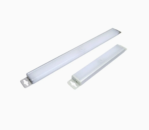
How Can Cabinet Lighting Wiring Be Improved for Long-Term Service?
Long-term reliability depends on standardized installation practices and suitable component selection. The lighting circuit should have a clearly defined supply, protection method, switching method, and wiring route. Components should remain accessible enough for replacement without disturbing critical equipment. Door switches require particular attention because mechanical movement occurs repeatedly throughout the cabinet life. Flexible conductors should have sufficient movement allowance without excessive slack. Lighting fixtures should also provide suitable thermal and environmental performance for the cabinet interior. In humid locations, designers should consider condensation and insulation conditions. In dusty environments, contamination can reduce illumination and affect electrical components. Documentation should identify every lighting circuit and its associated protective device. Future modifications should follow the same wiring philosophy. These practices make switchgear light wiring easier to inspect and maintain. They also help reduce avoidable faults caused by poor routing, loose terminals, incorrect voltage, or unsuitable component placement.
FAQ
Can a Switchgear Light Use the Cabinet Auxiliary Power Supply?
A switchgear light can use an auxiliary cabinet supply when the lamp rating matches the available voltage and circuit conditions. The designer should first confirm the supply type, voltage, frequency, and permissible load. DC and AC lamps require compatible electrical characteristics. The lighting branch should also have suitable protection and clear circuit identification. Connecting a lamp directly to an unrelated control circuit can create unnecessary service problems. Designers should consider what happens if the auxiliary supply becomes unavailable. Some applications may require cabinet lighting during specific maintenance conditions, while others accept loss of lighting with the auxiliary system. The selected arrangement should therefore follow the cabinet electrical design and project requirements. Proper testing should confirm normal lamp operation, switching performance, and protection behavior before the cabinet enters service.
Should a Switchgear Light Have Separate Circuit Protection?
Separate circuit protection can make cabinet lighting easier to isolate and maintain. A dedicated fuse or circuit breaker can limit the effect of a lighting fault on other auxiliary circuits. The protective device should match the conductor capacity, lamp load, and expected fault conditions. Its rating should also coordinate with upstream protection. An oversized device may provide inadequate conductor protection, while an unsuitable low rating may cause unnecessary interruptions. The protection device should remain clearly labeled on the electrical drawing and inside the cabinet. Maintenance personnel can then identify the correct isolation point without disturbing unrelated equipment. The final protection method depends on the cabinet design, applicable standards, supply arrangement, and manufacturer requirements. A qualified electrical designer should verify the complete circuit before commissioning.
Is a Door Switch Necessary for a Switchgear Cabinet Light?
A door switch is not always necessary, but it can provide useful automatic control. Cabinets with frequent inspection access can benefit from illumination that activates when the door opens. Manual switching may suit cabinets where operators need independent control or where access patterns vary. Some installations can combine automatic and manual functions when the auxiliary circuit supports that arrangement. The door switch should have suitable electrical contacts and sufficient mechanical durability. Its mounting position must allow consistent operation without affecting the door gasket, latch, or hinge. Wiring between the fixed cabinet and moving door should also tolerate repeated movement. The choice should reflect the maintenance procedure, cabinet construction, and control philosophy. Whatever method is selected, technicians should test the complete operating sequence before final commissioning.