
Switchgear Light Compatibility: How to Check Fit
Check switchgear light compatibility before replacement. Compare supply voltage, mounting, door controls, protection ratings, and lighting.
What Determines Switchgear Light Compatibility?
Switchgear light compatibility depends on the auxiliary supply, mounting interface, control method, environment, and visibility inside the compartment. Start with the exact cabinet and lamp variants. Check the existing lighting circuit drawing, fixture label, and the proposed replacement datasheet. Record the cabinet revision because earlier builds may use different harnesses or brackets. Compare how the original lamp operates during normal service and planned maintenance. Define which functions the replacement must preserve before evaluating available models. Keep any unknown rating open for engineering review.
Compare the Full Auxiliary Supply Range
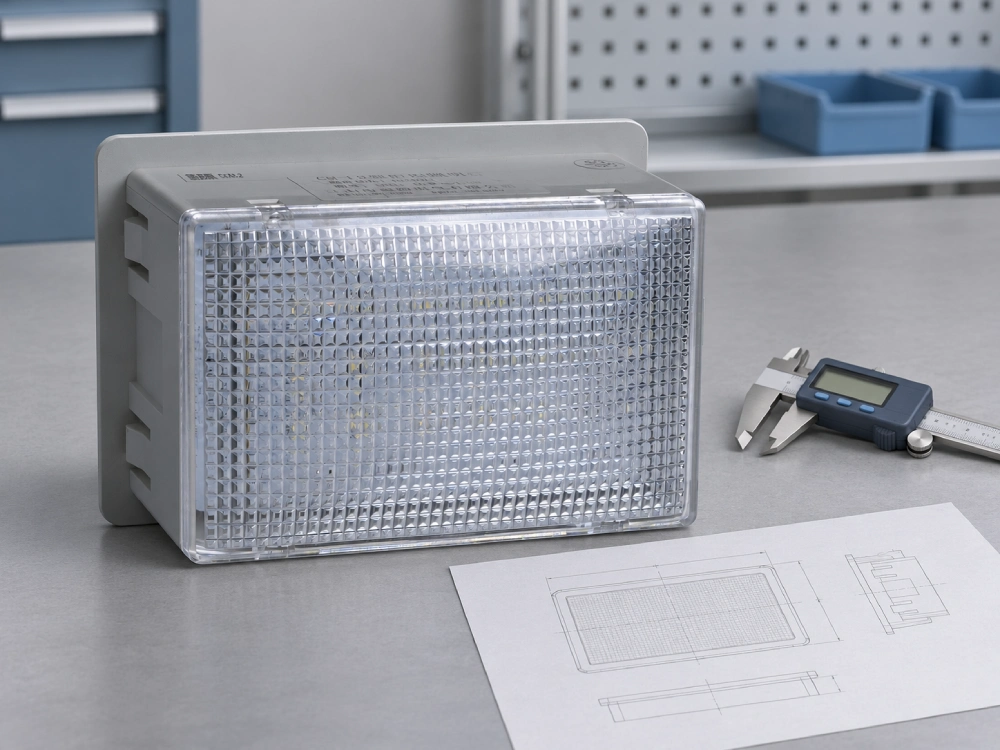
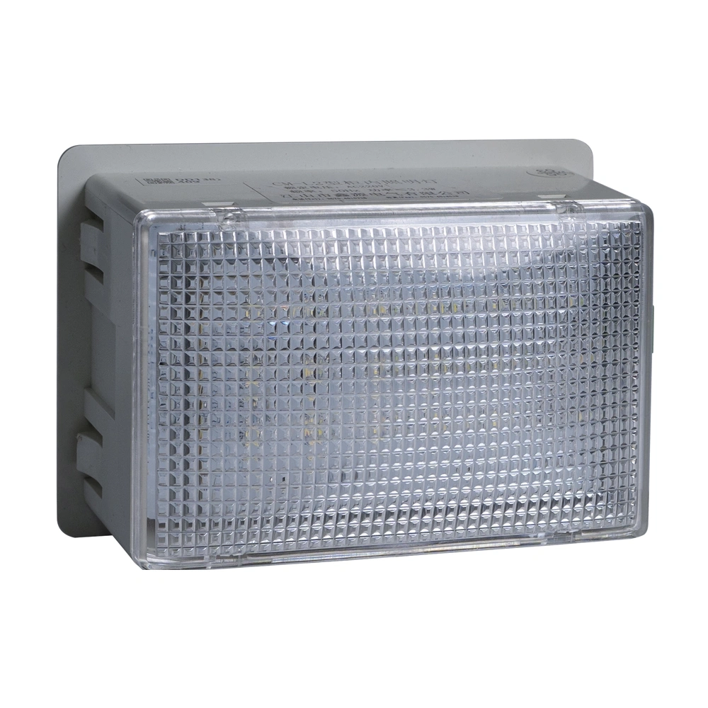
Check the actual lighting feed at its specified connection point. Record AC or DC, frequency where applicable, and the permitted operating range. For battery backed supplies, compare documented minimum and maximum bus voltages with the fixture limits. The CM-L2 cabinet LED light lists an 85–240 V AC/DC input range. By comparison, the LL10-W cabinet light lists 110–230 V AC/DC. Neither published range covers a 24 V DC feed. Compare the selected variant’s documentation before ordering. Where the ranges overlap, continue with control, fit, and environmental checks.
Identify What the Door Switch Controls
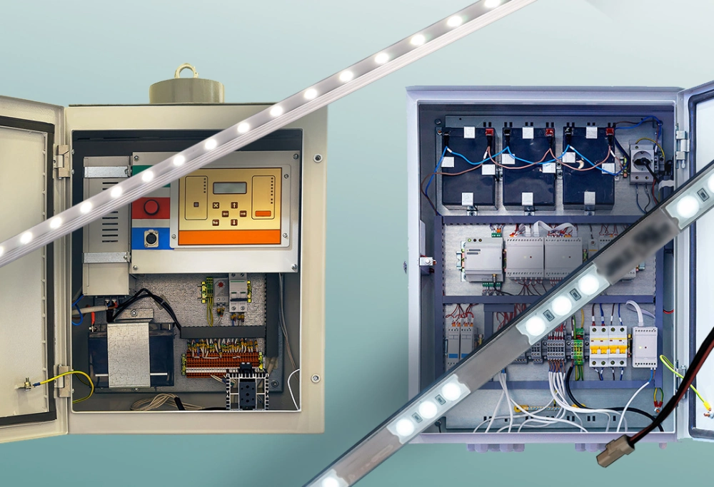
Trace the door switch on the approved schematic before reusing it. Some contacts switch lamp power directly. Others send a signal to a relay or controller. Match the proposed lamp to that circuit arrangement and the required door behavior. For direct switching, review the contact’s load rating and any driver inrush data. With a control input, verify its signal requirements and expected contact state. A connector that mates mechanically can still assign power and control to different pins. Ask the supplier for the pin assignment and compare it with the existing harness drawing.
Check the Mounting Interface and Service Access
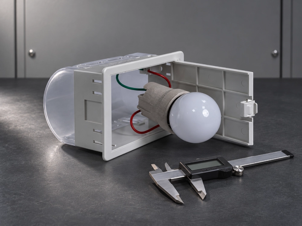
Compare both drawings at the mounting surface, using the same reference edge. Confirm the fixing pattern, panel thickness limits, and clearance behind the lamp. Account for the mating plug and cable bend when checking the installed depth. Then check the complete door movement with neighboring equipment in place. A shallow lamp may still obstruct a connector during removal. Where a bracket would bridge different fixing patterns, request approval for the revised arrangement. The review should cover retention, clearances, and any effects on cabinet partitions or seals.
Compare the Compartment Conditions and Light Pattern
Review temperature and moisture at the actual mounting location. A cabinet’s external protection rating describes the enclosure and cannot establish the lamp’s own suitability. Compare the fixture limits with local conditions near heaters, ventilation openings, or condensation paths. Check the intended tasks from the normal service position. Two lamps with similar lumen ratings can illuminate terminals differently because their lenses distribute light differently. Compare label readability, shadows behind ducts, and reflections on instrument covers. Use the cabinet’s acceptance criteria for any quantitative illumination checks.
Record the Switchgear Light Compatibility Decision
Classify each candidate as a direct replacement, an engineering change, or unsuitable for the current cabinet. An unverified interface needs evidence before a direct replacement decision. Ask qualified personnel to validate the approved configuration under the equipment instructions and site procedures. Record the exact lamp variant, cabinet revision, supporting drawings, and acceptance results. Where engineering approves a new bracket or harness, identify that change on the replacement record. This keeps purchasing and service teams from treating a cabinet specific approval as universal. Recheck switchgear light compatibility when either product revision changes.
| Interface | Evidence to compare | Reason to hold approval |
|---|---|---|
| Supply | Compare actual AC or DC limits with the variant rating | Operating range falls outside the fixture rating |
| Control | Compare contact role, load rating, and pin assignment | Unverified connection or switching behavior |
| Mounting | Check the drawing, installed depth, and removal path | Interference or an unapproved bracket change |
| Environment | Compare local conditions with the lamp limits | Exposure exceeds the documented rating |
| Visibility | Check labels and service points in the complete cabinet | Task visibility misses the acceptance criteria |
Frequently Asked Questions
Can a Wide Voltage Lamp Run on a 24 V DC Supply?
Only if the exact variant’s DC input range covers the lighting supply throughout its specified operation. Read the DC limits separately from any AC rating. Check the supply documentation for the minimum and maximum values, including battery conditions where relevant. A nominal label alone gives an incomplete comparison. Also verify polarity and the approved protective arrangement with the fixture documentation. Where the range excludes the supply, select an appropriately rated variant or obtain approval for a redesigned feed. A brief functional test cannot establish suitability outside the published range. Document the accepted supply limits with the replacement part number.
Can I Reuse the Existing Door Switch and Connector?
Reuse depends on the circuit role, contact rating, pin assignment, and behavior with the proposed fixture. Start with the approved schematic and identify the expected light state for each door position. Check whether the contact switches the load or signals a controller. Ask for the lamp’s electrical interface and relevant switching data. Similar housings can conceal different terminal assignments. If the interface differs, have engineering review the necessary switch or harness change. Qualified personnel should verify the resulting operation under the approved test plan. Record the compatible connector and switch references for future repairs.
What Evidence Supports a Direct Replacement Decision?
Use the original and replacement drawings, fixture ratings, and cabinet wiring diagram. Compare their mechanical and electrical interfaces against the exact cabinet revision. Check rear clearance with the cable connected and verify that the door clears the complete fixture. Confirm that the environmental limits cover the mounting location. Inspect visibility at the actual service points under the project’s acceptance conditions. Keep photographs and test results with the approved replacement record. A model that needs a different mounting pattern or wiring arrangement should enter the engineering change process. Procurement can then order the approved variant with its required accessories.