
Switchgear Light Dimensions: A Cabinet Fit Guide
Check switchgear light dimensions before ordering. Compare panel cutouts, mounting patterns, depth, cable bends, and service clearance.
Measure the Space the Fixture Needs
Switchgear light dimensions describe the fixture body, its cutout or mounting pattern, and the space it needs in service. A housing can fit between two rails while its plug still hits a wire duct. Start with the actual mounting surface and the nearest obstacles. Then check how the fixture moves during installation, connection, and removal. Use the dimensions for the exact model and mounting option.
Read Switchgear Light Dimensions on the Drawing
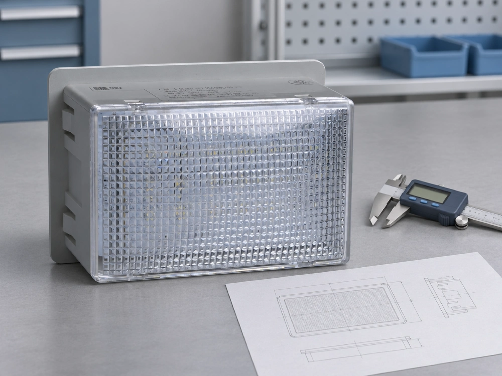
Find the overall length, width, and depth on the outline views. Locate the mounting face before measuring how far the fixture projects into the cabinet. For a panel mount, distinguish the cutout from the visible bezel. Check panel thickness, corner radii, and the cutout tolerance. For a rail mount, identify hole centers, slot sizes, and offsets from a fixed edge. A rail's hole pitch describes its repeating pattern. Fixture hole spacing describes the distance between its mounting points. Compare these values using the same origin and orientation. Follow the printed dimensions rather than scaling a catalog image.
Compare the CM-1 and CM-L2 Drawings
The CM-1 Cabinet Light and CM-L2 Cabinet LED Light drawings show the same nominal panel opening. Both specify a 107.5 × 71 mm cutout and a 117.5 × 81.5 mm front outline. Their side views show overall depths of 87.7 mm and 52.6 mm, respectively. These depths run across the entire side profile. Measure rear projection separately from the mounting face. Before machining, confirm cutout tolerances and acceptable panel thickness for the exact variant.
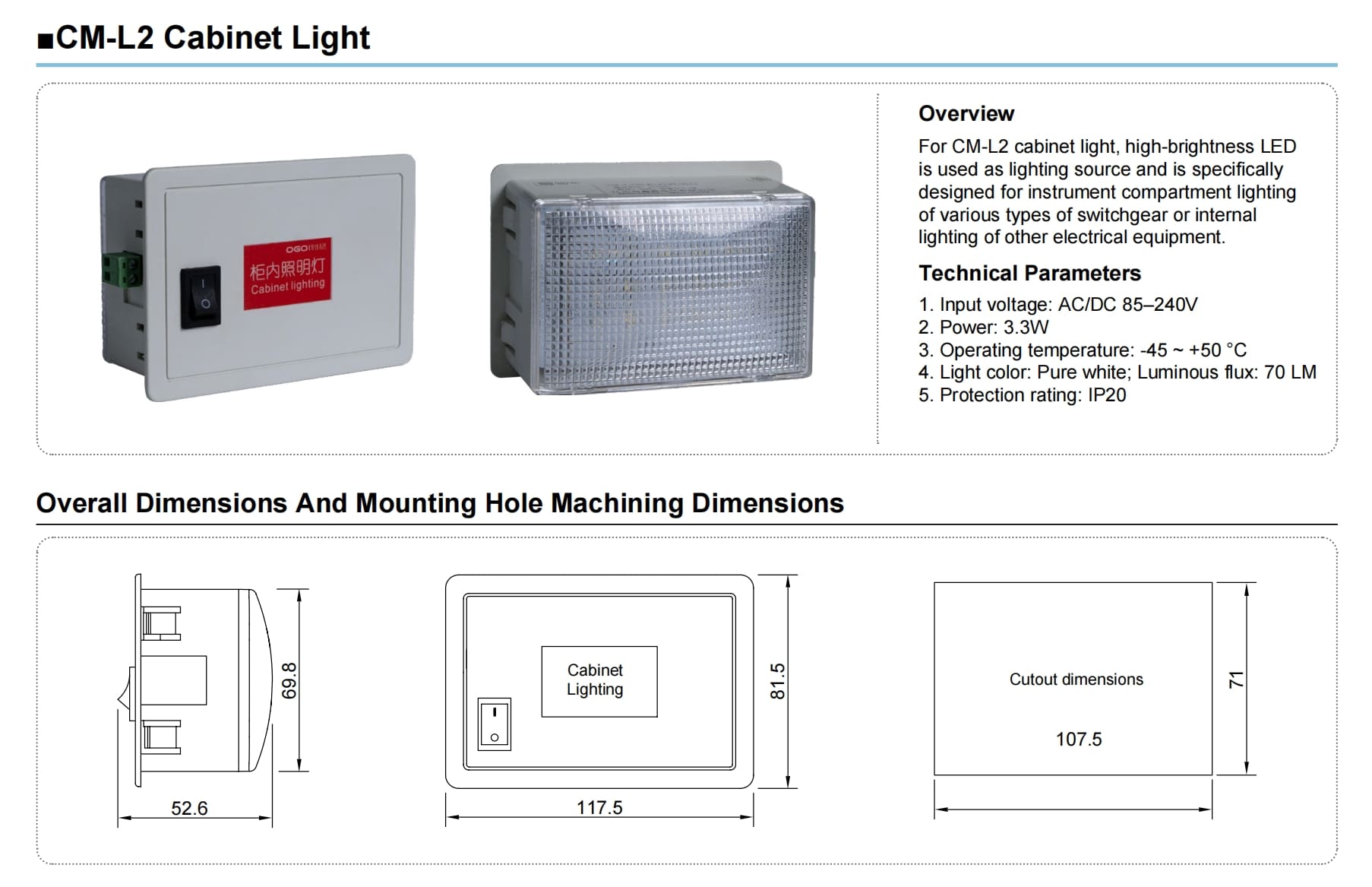
Check Switchgear Light Dimensions Against the Cabinet
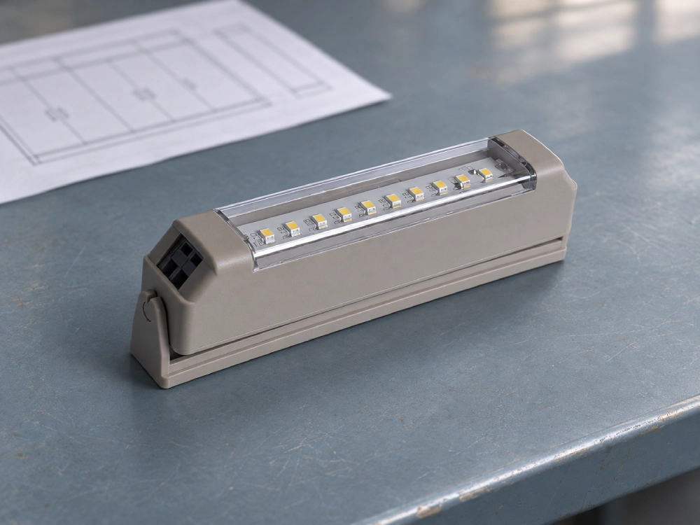
Measure the shortest clear span at the intended mounting position. Include the fitted brackets, standoffs, and screw heads when checking depth. Allow for the plug body and cable route in the installed footprint. For example, a 240 mm body and 35 mm end projection occupy 275 mm along the same axis. A 280 mm opening then leaves just 5 mm before tolerances and service allowances. Treat those figures as a layout example. Take the actual projection from the connector drawing and cable specifications.
Measurements to record before releasing the layout
| Check | What to record | What it can catch |
|---|---|---|
| Body outline | Overall length and width, plus depth from the mounting face | Interference with rails, ducts, or panels |
| Fixing pattern | Panel cutout or hole pattern, including size and offsets from a fixed edge | Mounting points that do not align |
| Connected footprint | Plug projection, cable exit direction, and minimum bend radius | A cable path that needs more room |
| Moving parts | Closest approach of the door, latch rod, and door harness | Contact during opening or closing |
| Service access | Tool approach, connector withdrawal, and fixture removal path | A fixture that fits but cannot come out |
Check the Door Swing and Removal Path
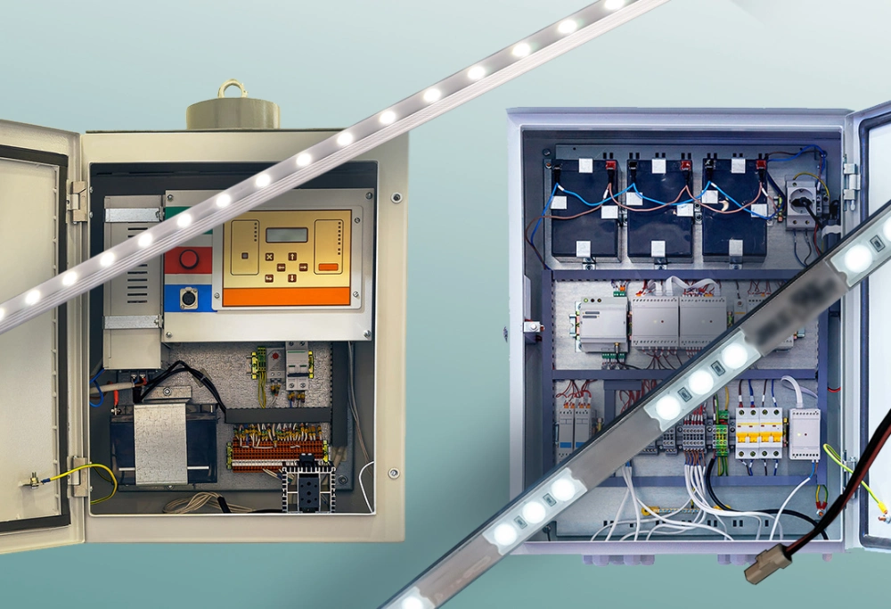
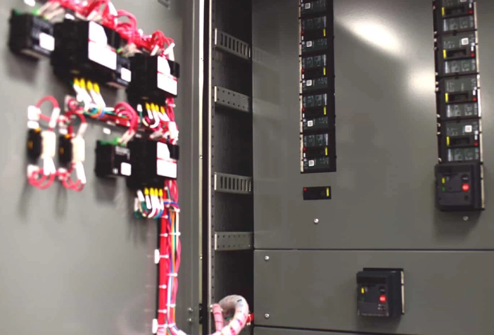
Review the door through its full travel with the equipment in a safe, isolated condition. A door harness or latch rod can pass closer to the fixture midway through the swing. Model that movement in the layout or use a full size mockup during a fit check. Allow space to release the connector latch and withdraw the plug. Check tool access and allow room for any hinged service cover. Keep the cabinet manufacturer's required clearances and barriers in the layout.
Record Tolerances Before Releasing the Layout
Switchgear light dimensions belong on the layout alongside the model code, drawing revision, and mounting hardware. Compare the smallest available space with the largest installed footprint. Use documented limits for rail position, bracket thickness, and fixture size. Then confirm that the remaining gap meets your project requirements. A fit check on one sample can verify access. The tolerance review shows whether later units can fit the same layout.
Frequently Asked Questions
Is there a standard length for switchgear lights?
There is no single length you can use for every fixture. Manufacturers offer different housings and mounting options, sometimes within one product family. Panel fixtures may instead specify a rectangular cutout and front outline. Use the exact model code to locate the outline and fixing views. Record the body length separately from the space needed at either end. One end may need room for a plug, even when the housing fits. Compare the total installed footprint with the clear span at the chosen mounting location. If the drawing omits a critical dimension, request it before committing to the cabinet layout.
Can I reuse the old holes if the new fixture has the same length?
Sometimes, but matching body lengths tell you little about the fixing pattern. Measure hole centers from the same reference edge on both fixtures. Compare diameter, slot direction, mounting face, and hardware access. For a slot, check its usable adjustment range with the specified fastener. Verify that the bracket seats flat and leaves room to tighten the hardware. If the holes do not align, ask the cabinet designer to review an approved bracket or mounting location. Include any added bracket depth in the fit check before approving the replacement.
How much extra space should I leave for a plug and cable?
Use the specified connector and cable to determine the allowance. Measure the plug projection in its seated position first. Next, check how far it must move to disengage and whether you can reach its latch. Route the cable using its specified bend radius, then check the nearest duct or door harness. A side exit can shift the space requirement from length to depth or width. Confirm the route at the tightest point and check service access separately. Use a sample or full size layout when the remaining space is small.