
Switchgear Light Assembly: Parts, Fit, and Final Checks
Switchgear light assembly requires compatible parts, secure mounting, clear wiring, and functional checks for consistent cabinet production.
What Does a Switchgear Light Assembly Include?
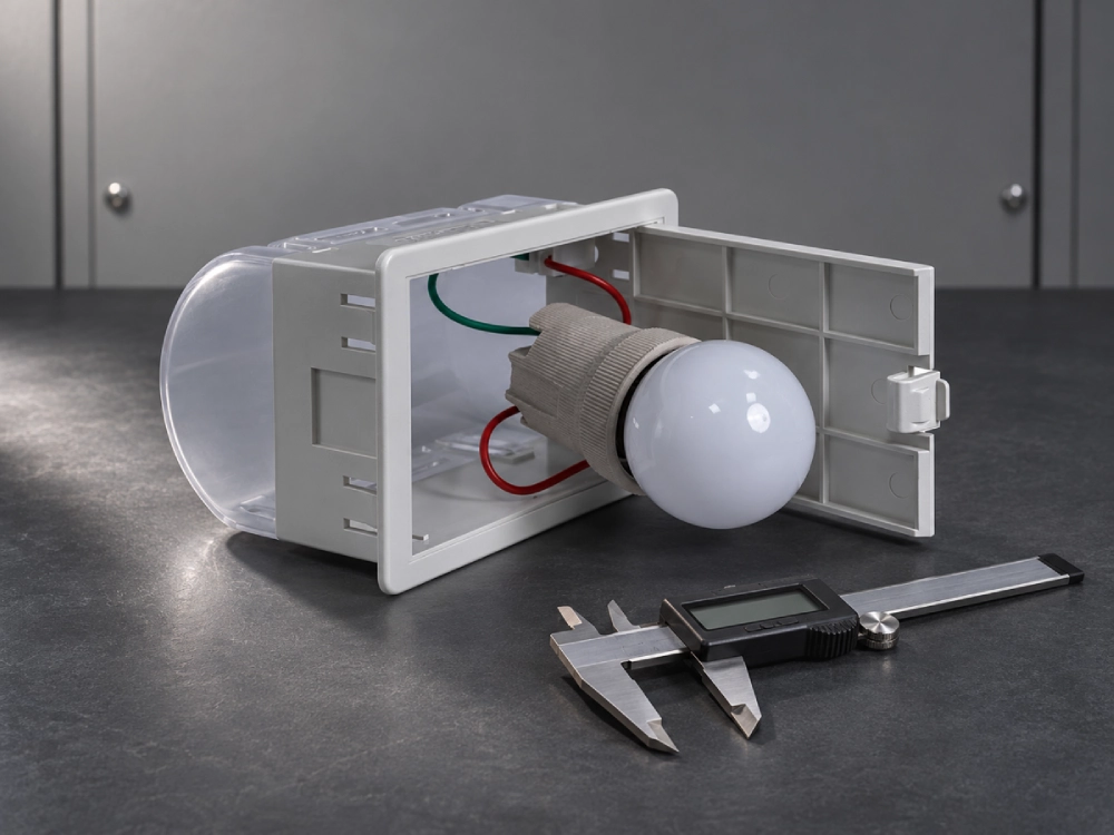
A switchgear light assembly combines the lamp, mounting components, electrical connections, and any specified switching accessories. Buying the fixture alone does not necessarily provide a complete installation kit. Cabinet builders should define the supply boundary before releasing a production order. Separate included components from items that the panel workshop must provide. Typical records identify the lamp variant, mounting arrangement, connector details, and control interface. Some designs use a manual switch; others use an approved door contact or sensor. Confirm those functions for the actual model rather than assuming every lamp supports them. Assembly quality depends on how these parts work together, not simply whether the lamp illuminates.
Freeze the Parts List Before the First Build
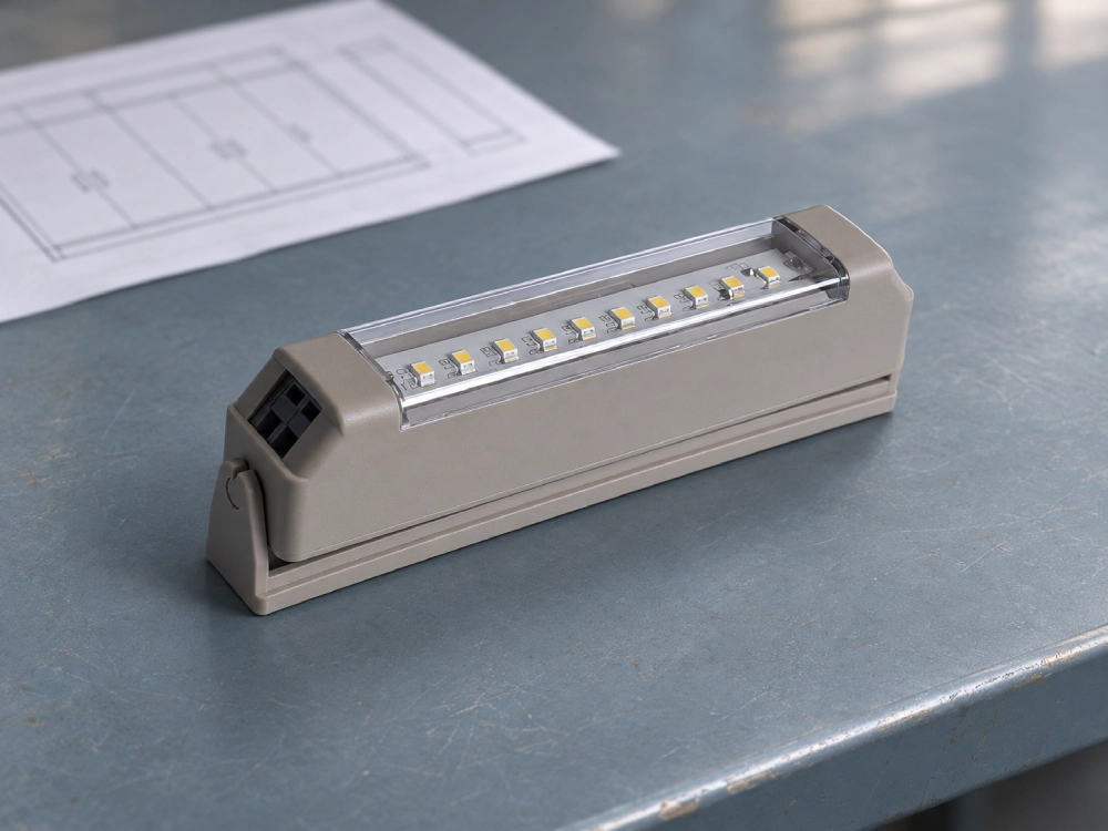
Use a controlled bill of materials that identifies each part and drawing revision. The CM-L2 Cabinet LED Light for Switchgear provides an LED example for checking model-specific requirements. Its published input range does not include 24 V DC, so avoid assuming universal auxiliary-supply compatibility. The CM-1 Cabinet Light for Switchgear uses a different lamp arrangement and needs its own assembly review. Similar front dimensions do not establish equivalent mounting, heat output, or service access. List fasteners, terminals, conductor identification, and switching accessories separately. Record whether the order includes each item or requires workshop sourcing. Approve substitutions before kitting parts, especially when connectors look similar but have different ratings or pin arrangements.
Check the Mounting and Service Envelope
A fixture that fits the opening may still prevent routine maintenance. Review the flange, housing depth, connector access, and space needed to remove the cover or replace the unit. Use the approved drawing to define hole positions and permissible dimensional variation.
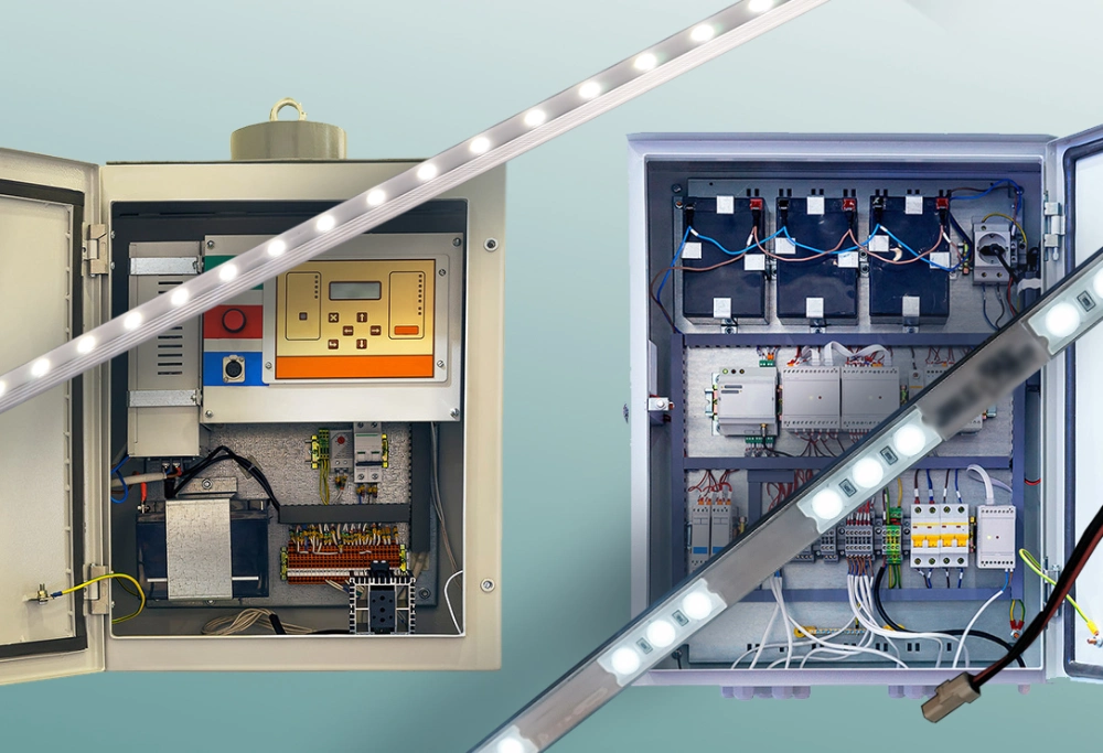
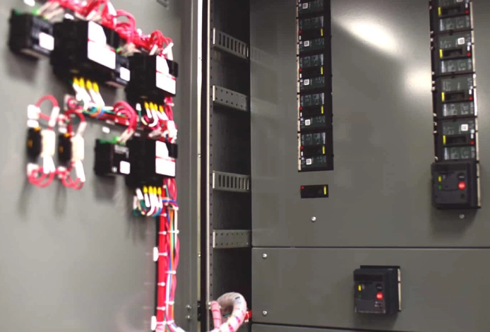
A production jig can repeat those positions, but first validate it against the cabinet reference surfaces. Check the fully populated compartment rather than an empty enclosure. Terminal covers, cable ducts, and door hardware can create conflicts after the initial fitting. Evaluate light coverage from the technician’s working position and check shadows around labels. Keep optical performance separate from mechanical fit. Do not change compartment barriers or required electrical clearances simply to accommodate a lamp.
Review the Supply and Switching as One Circuit
Confirm the actual supply type, operating range, and required lighting behavior before approving the harness. Cabinet voltage alone does not identify the supply available at the lighting connection. Some auxiliary circuits can remain energized after the main equipment disconnect opens. Qualified personnel should identify and isolate every relevant source under the approved site procedure before electrical work. Select protection and switching devices against the lamp manufacturer’s data and cabinet design. An LED load can impose switching demands beyond its steady operating current. Check the specified control interface instead of assuming a door contact directly switches lamp power. Automatic illumination provides convenience; it does not establish electrical isolation or permission to access hazardous compartments.
Standardize Harnesses, Fixings, and Part Orientation
Define harness length, termination details, and routing references in the assembly instruction. Support the cable so its weight does not pull on the lamp connection. Where wiring crosses a moving interface, assess the full movement range and the cable manufacturer’s bending requirements. Match fasteners and tightening values to the approved fixture and mounting surface. Excess force can damage plastic components even when the screw initially feels secure. Avoid drilling or machining near exposed internal equipment without the cabinet manufacturer’s approved controls. Remove resulting debris before closing the compartment. Check brackets, connectors, and covers for correct orientation during the first build. Photographs can clarify approved routing, but they should supplement dimensioned drawings rather than replace them.
Verify the Complete Switchgear Light Assembly
First-article review should confirm the complete arrangement before repeating it across a cabinet series. Inspect component identification, mounting security, connector engagement, and access for future replacement. Qualified personnel should perform electrical checks under the approved test plan. Match any insulation testing to equipment instructions; electronic drivers may require special treatment. Then verify the intended manual, door-controlled, or sensor-controlled operation where the model supports it. Evaluate illumination with the actual cabinet contents and normal service viewing position. A working lamp can still leave essential labels unreadable or create distracting reflections. Compare results against the project’s defined acceptance criteria instead of inventing a universal brightness threshold. Use the following record to capture evidence and unresolved issues.
| Assembly check | Evidence to retain | Reason to hold release |
|---|---|---|
| Configuration | Part numbers and approved revisions | Unapproved component substitution |
| Mechanical fit | Drawing review and first-article photographs | Obstruction, loose fixing, or inaccessible cover |
| Harness | Connector, routing, and identification checks | Strain, pinching, or incorrect termination |
| Control function | Results for each specified operating mode | Incorrect switching behavior or unstable operation |
| Task visibility | Observations at agreed inspection locations | Unreadable labels or unacceptable reflections |
Release a Build Record That Supports Future Repairs
The final record should identify the approved parts list, drawing revision, routing reference, and inspection results. Link that record to the cabinet identifier so service teams can find the correct configuration later. Keep component replacements under revision control when they affect fit, electrical compatibility, or maintenance access. A replacement light may require a new bracket or harness even when its nominal supply matches. Store approved spare-part references alongside the service instructions. For repeat switchgear light assembly, carry forward the validated configuration rather than rebuilding decisions from memory. Review changes through engineering before purchasing substitutes. This approach supports consistent production without treating every accessory change as automatically interchangeable.
Frequently Asked Questions
Does a Cabinet Light Include Its Mounting and Wiring Parts?
Not necessarily. A product listing may cover only the fixture, while the cabinet builder supplies brackets, fasteners, connectors, or cables. Request an itemized scope before ordering samples or production quantities. Confirm whether a door switch, mating connector, and protective components form part of the package. Also check whether the supplier provides installation drawings and model-specific instructions. A mounting accessory from another lamp family may fit visually without meeting retention or clearance requirements. Record the accepted kit contents in the bill of materials. This prevents workshop substitutions and helps buyers compare quotations with equivalent supply boundaries.
Can a Door Switch Make the Compartment Safe to Access?
No. A door switch can control illumination, but its operation does not prove that hazardous electrical energy is absent. Lighting controls and the cabinet’s protective functions serve different purposes. Opening a door can activate the lamp while other circuits remain energized. Some designs also retain a separate auxiliary lighting supply after the main disconnect opens. Follow the equipment manufacturer’s access rules and the site’s approved isolation and verification procedures. Qualified personnel should confirm the relevant circuit conditions before electrical work. During assembly review, identify the lighting source and document any independent supply clearly. Never interpret a lit or unlit lamp as an electrical safety indication.
Can an LED Model Replace an Existing Lamp Without Other Changes?
Sometimes, but matching the nominal voltage alone does not establish compatibility. Check the permitted input range, mounting geometry, housing depth, terminals, and switching requirements. Review the replacement’s heat output, operating environment, and access needs against the existing compartment. Its connector may also require a different mating part or harness. Test the proposed arrangement against the approved acceptance criteria before releasing a production change. Keep the original cabinet drawings and parts list consistent with the final configuration. Where the manufacturer prohibits opening or repairing the fixture, follow its replacement instructions. Approve the complete modification rather than treating the new lamp as an isolated component.