How To Choose A Disconnect Locking Mechanism?
Disconnect locking mechanism selection depends on equipment fit, locking position, materials, durability, environment, and lock type.
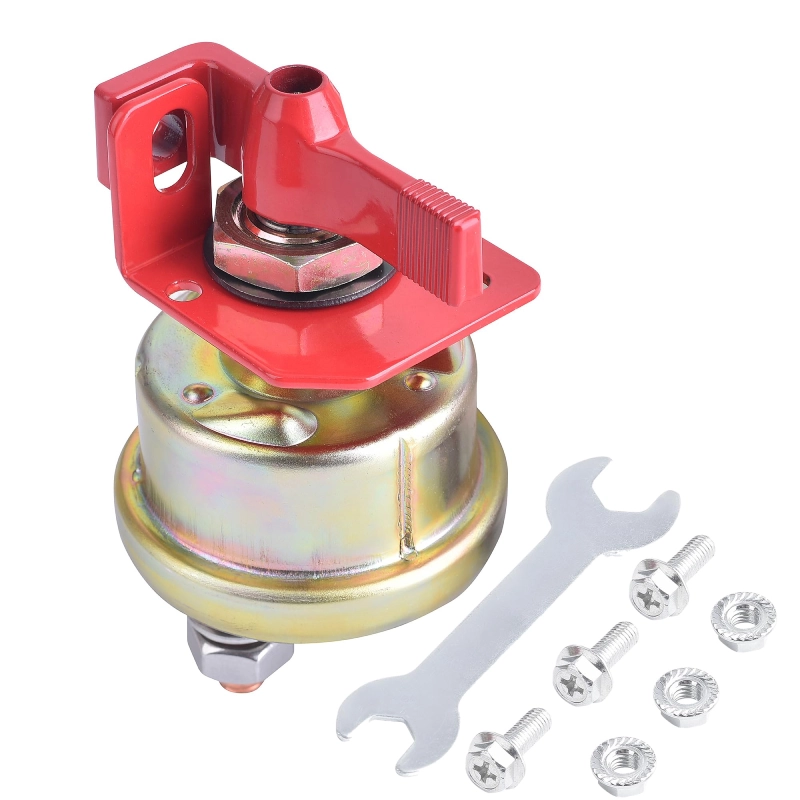
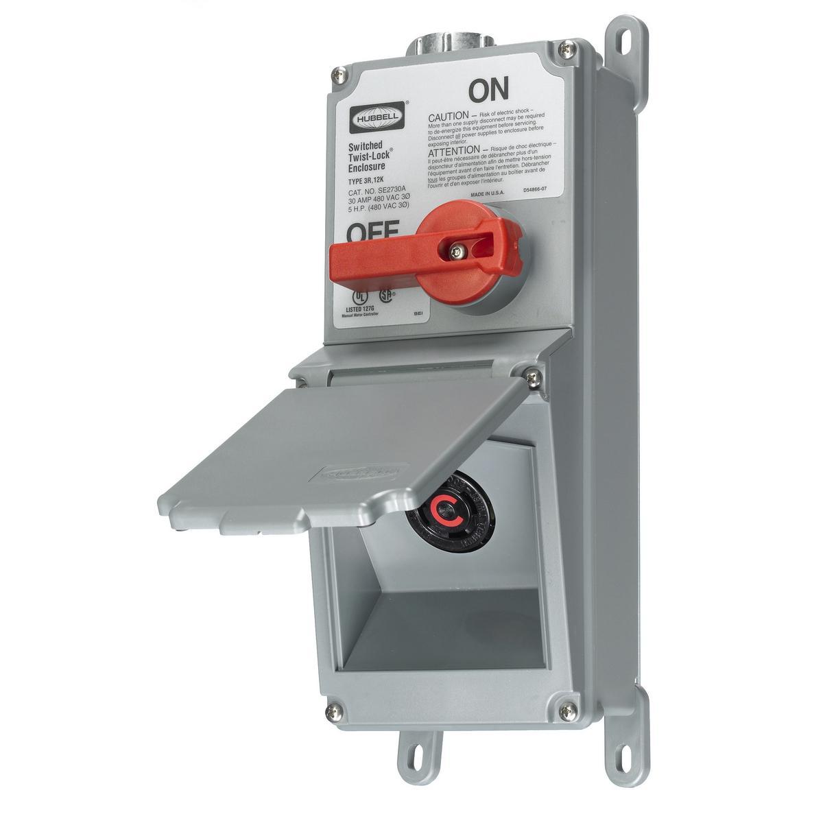
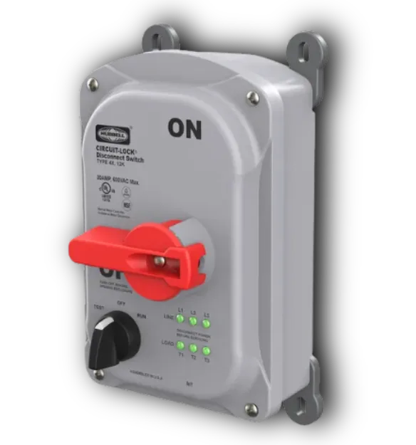
A disconnect locking mechanism should match the equipment and its operating environment. Start by identifying the disconnect type, enclosure design, and operating method. Check whether operators use a rotary handle, sliding actuator, or external lever. Record the equipment model and manufacturer before comparing products. Operating frequency also matters because frequent maintenance can increase mechanical wear. Outdoor installations need stronger resistance to moisture, dust, and temperature changes. Indoor switchgear may face less exposure but still needs dependable mechanical performance. Maintenance procedures should define when operators need isolation and how they verify it. These details create a practical selection baseline. They also reduce the risk of choosing a device that fits physically but fails during routine operation. Site conditions should therefore shape every later specification decision.
Equipment Structure Determines Compatibility
Equipment dimensions often decide whether a locking device can install correctly. Inspect the handle shape, shaft position, mounting holes, and available clearance. Measure the handle travel before selecting a locking structure. Some assemblies need clearance around the actuator during rotation. Others require a fixed bracket that surrounds the operating point. Check nearby doors, covers, cable entries, and protective barriers as well. A compact design can help when enclosure space remains limited. However, compact construction should not restrict normal operator movement. Manufacturers should provide dimensional drawings for accurate comparison. Buyers can then compare mounting dimensions against the actual equipment. A small mismatch can prevent secure installation or create unwanted movement during operation. Record every critical dimension before approving a sample.
Disconnect Locking Mechanism Positions Need Clear Mechanical Control
A disconnect locking mechanism should control the intended operating position without creating extra hazards. Confirm whether the equipment supports OFF, ON, or an isolated maintenance position. The locking point should remain stable under normal handling forces. Operators should also see the equipment status without removing protective components. A good design prevents accidental movement while allowing authorized maintenance procedures. Locking geometry matters because loose engagement can create unwanted actuator travel. Check whether the mechanism blocks movement directly or relies on another component. Direct mechanical restraint usually gives clearer feedback during inspection. Buyers should document the permitted positions before placing larger orders. That specification also helps quality teams verify samples consistently. Clear position control also supports repeatable maintenance procedures across equipment groups.
Materials Influence Service Life
Material selection affects corrosion resistance, stiffness, wear behavior, and service life. Stainless steel suits demanding environments where moisture or chemical exposure may occur. Engineering plastics can reduce weight and provide electrical insulation around selected components. However, plastic grades differ greatly in impact strength and temperature resistance. Metal parts should also receive suitable surface treatment when corrosion risks exist. Zinc plating, passivation, or protective coatings can support longer service in suitable environments. Material choices should match the actual exposure rather than marketing claims. Coastal sites may require stronger corrosion protection than clean indoor rooms. Industrial areas can also expose components to oils, dust, and cleaning chemicals. Buyers should request material specifications and surface treatment details before approval. These records help quality teams verify material consistency during production.
Material Selection Criteria
| Material | Main Advantage | Typical Concern | Suitable Environment |
|---|---|---|---|
| Stainless steel | High corrosion resistance | Higher material cost | Moisture and industrial exposure |
| Engineering plastic | Low weight and insulation | Grade-dependent impact resistance | Controlled indoor applications |
| Plated steel | Strong mechanical performance | Coating damage can expose steel | General industrial use |
| Aluminum | Low weight and good corrosion resistance | Lower hardness than steel | Lightweight equipment assemblies |
Material choices become clearer when buyers connect them with site conditions. Stainless steel offers a strong option for humid or corrosive locations. Engineering plastic may work well where insulation and low weight matter. Plated steel can provide a practical balance for controlled environments. Aluminum can reduce assembly weight when the design permits lower surface hardness. The correct choice depends on load, exposure, temperature, and maintenance practices. Buyers should request certificates or material declarations for critical components. Visual appearance alone cannot confirm alloy grade or protective performance. Sample testing can reveal coating adhesion, fit, and mechanical behavior. These checks create stronger evidence than relying on catalog descriptions alone. Specifications should state the selected material clearly.
Lock Compatibility Requires Exact Measurements
Lock compatibility can affect whether operators can use the mechanism efficiently. Check the supported lock shackle diameter and available shackle clearance. Multi-user maintenance may require a hasp arrangement with several locking points. Operators also need enough space to insert and remove locks without awkward movement. A locking point that sits too close to the enclosure can slow maintenance. Record the preferred lock dimensions before approving a final configuration. Consider padlock body size as well as shackle diameter. Oversized locks may interfere with doors or neighboring equipment. Small locks may lack sufficient clearance for practical handling. A dimensional review prevents many installation problems before production begins. Selection should include these measurements from the start.
Critical Parameters For Technical Comparison
- Shackle diameter and usable locking clearance
- Mounting hole diameter, spacing, and bracket thickness
- Handle travel, rotation angle, and actuator geometry
- Working temperature and environmental exposure
- Material grade, surface treatment, and corrosion protection
Dimensional data should drive the final compatibility decision. Buyers can create a simple comparison sheet using these parameters. Each candidate should meet the equipment dimensions and selected lock requirements. Installation drawings can reveal conflicts that product photos often hide. Handle travel deserves special attention because rotational movement needs adequate clearance.
| Parameter | What To Check | Why It Matters |
|---|---|---|
| Shackle diameter | Maximum supported diameter | Prevents incompatible padlock selection |
| Locking clearance | Space around the locking point | Supports easy insertion and removal |
| Mounting hole size | Hole diameter and spacing | Confirms bracket compatibility |
| Handle travel | Full operating movement | Prevents mechanical interference |
| Working temperature | Expected site temperature range | Supports material and component selection |
Technical data should remain the final reference during purchasing and inspection. Buyers can compare candidate products against actual equipment measurements. Each candidate should meet the required dimensions and locking conditions. Installation drawings can reveal conflicts that product photographs often hide. Handle travel deserves particular attention because rotational movement needs sufficient clearance. Temperature data also helps confirm whether plastic or elastomer components remain stable. For repeat purchases, keep the approved dimensions as a controlled reference. Future batches can then follow the same acceptance criteria. This approach reduces variation between suppliers and production lots. Inspectors can also use the same criteria during incoming quality checks. Consistent records make future replacement orders faster and more reliable.
FAQ
What Does A Disconnect Locking Mechanism Do?
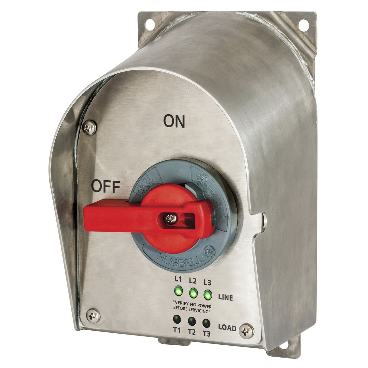
A disconnect locking mechanism restricts unwanted movement of an equipment actuator. It helps keep a selected operating position during maintenance or controlled access. The exact function depends on the equipment design and locking interface. Some mechanisms hold a handle in the OFF position. Others support specific isolation positions or multiple padlocks. Mechanical restraint should match the equipment manufacturer's operating procedure. Operators still need to follow the site's electrical isolation and verification process. The locking device does not replace electrical testing or established safety procedures. Buyers should confirm the intended locking positions before purchase. Physical compatibility also matters because a secure lock requires correct engagement. Proper selection supports consistent maintenance practices and reduces accidental actuator movement.
How Do I Know If A Locking Mechanism Fits My Equipment?
Start with the equipment model, actuator type, and mounting configuration. Measure the handle dimensions, travel distance, mounting holes, and available clearance.Check the supplier's dimensional drawing against those measurements. Then verify padlock shackle diameter and lock body clearance. Review nearby doors, covers, cables, and protective barriers for possible interference. A sample installation provides stronger evidence than photographs or general compatibility statements. Test normal operation before applying the locking function. After locking, verify that the actuator cannot move beyond the intended position. Record the approved dimensions and sample version for future orders. When equipment varies by series, evaluate each relevant model separately. This method reduces installation surprises and supports repeatable procurement decisions.
What Materials Work Best For Disconnect Locking Mechanisms?
No single material works best for every installation. Stainless steel often suits humid, outdoor, or corrosive industrial environments. Plated steel can provide strong mechanical performance for controlled conditions. Engineering plastics can offer low weight and electrical insulation for suitable designs. Material selection should consider impact loads, temperature, moisture, chemicals, and operating frequency. Surface treatment also affects corrosion resistance and service life. Buyers should request specific alloy grades or plastic grades when performance matters. Coating details can also help inspectors verify production consistency. Sample testing should cover fit, surface quality, and repeated operation. Environmental exposure may justify additional corrosion or temperature testing. The best material balances mechanical strength, environmental resistance, weight, cost, and expected service life.