
How To Choose The Right Cable Fault Indicator?
Cable fault indicator selection: compare detection methods, grounding, installation, communication, and maintenance costs.
Cable fault indicator selection is an important decision for reliable power distribution and efficient fault management. The right device helps maintenance teams identify faulted cable sections and reduce troubleshooting time. However, different networks require different detection functions, installation methods, and communication capabilities.
Buyers should evaluate more than the initial purchase price. Cable type, fault characteristics, detection thresholds, environmental conditions, and maintenance requirements all affect product suitability. Compatibility with existing distribution equipment also matters.
This article explains the key factors to consider when selecting a cable fault indicator. It also covers common purchasing mistakes and practical checks for electrical engineers, utilities, and equipment procurement teams.
What Should You Know Before Cable Fault Indicator Selection?
Before comparing products, define the network conditions and the problem the device must solve. A suitable indicator should match the electrical system, installation environment, and maintenance strategy.
Cable Fault Indicator vs. Cable Fault Testing System
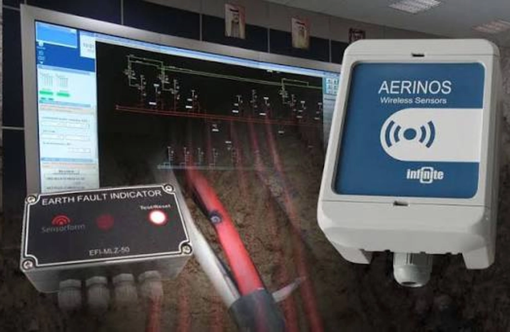
A cable fault indicator and a cable fault testing system serve different purposes. A fault indicator monitors electrical conditions and signals when it detects a qualifying fault. Technicians can inspect indicators along a circuit to narrow down the affected section.
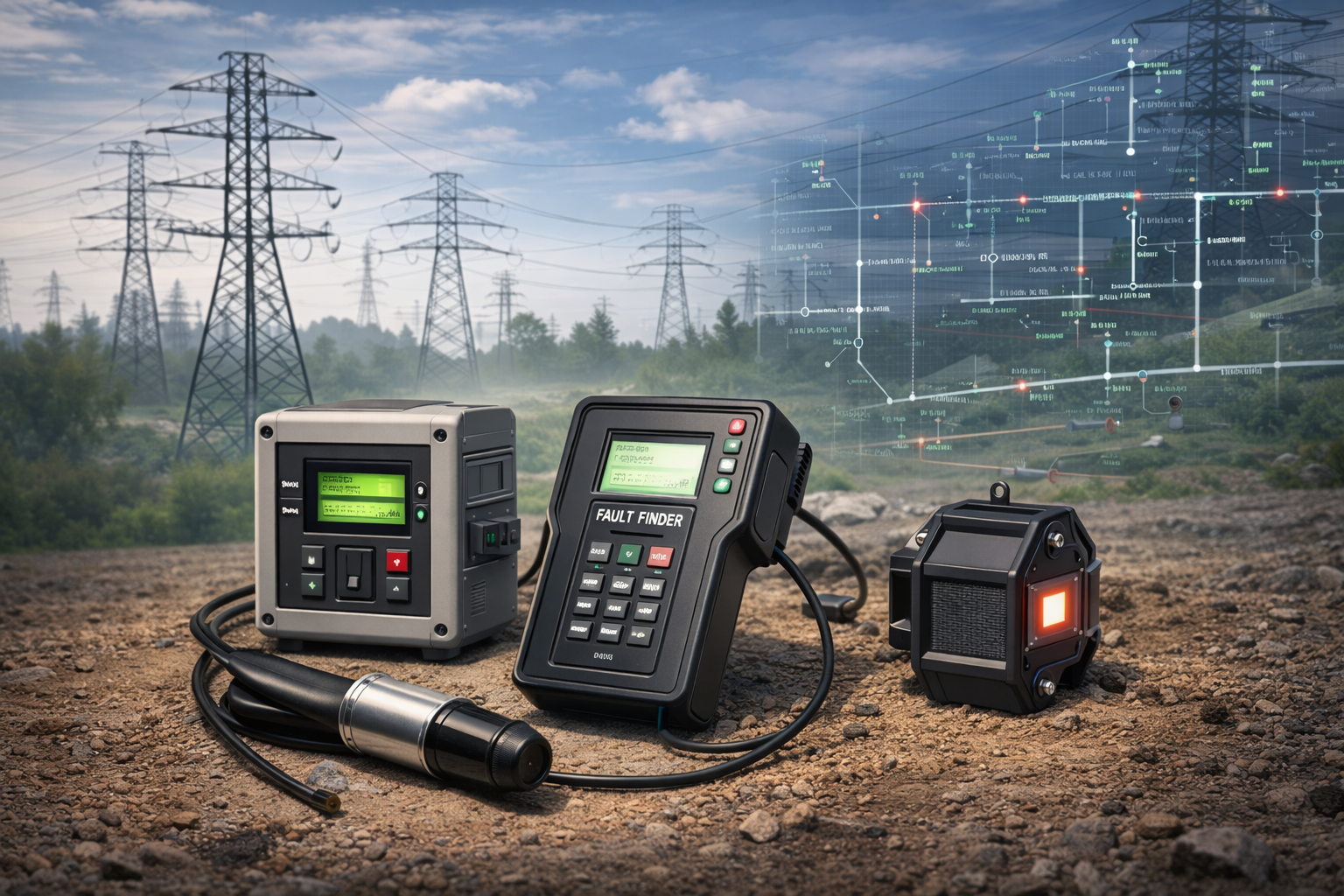
A cable fault testing system uses diagnostic methods to investigate cable condition or locate a fault more precisely. Depending on its configuration, it may measure fault distance and support pinpointing the damaged location. These systems often require technicians to perform specific testing procedures.
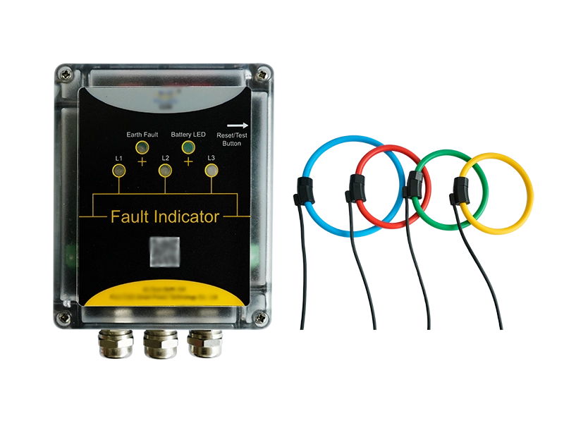
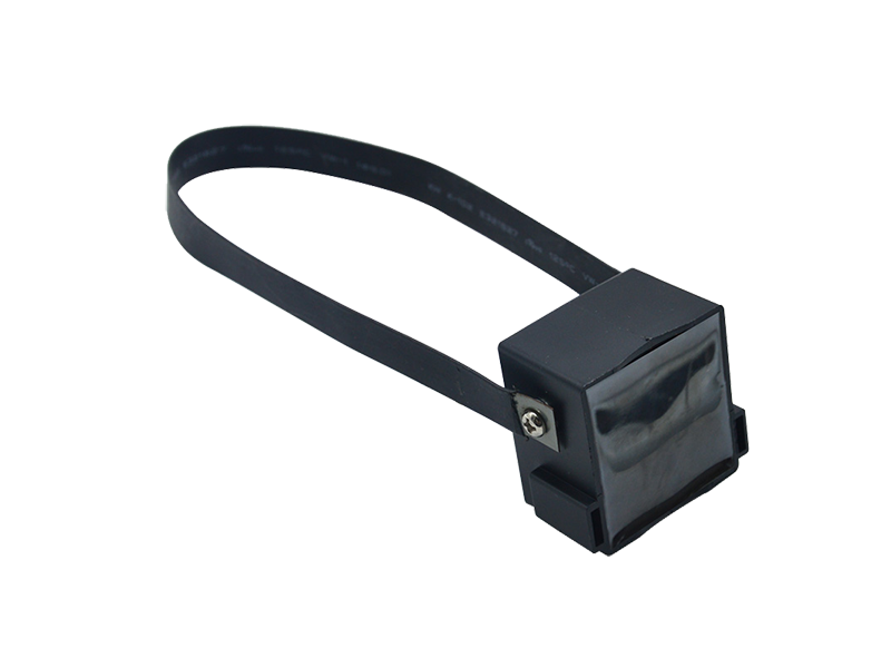
For distribution networks, indicators can help maintenance teams identify where a fault has occurred. Testing equipment may then support further diagnosis and repair. Buyers should choose according to their operational needs rather than treating the two product categories as interchangeable.
Identify the Cable Network and Application
Start by confirming the rated voltage, cable construction, network topology, and installation location. Consider whether the device will serve an underground distribution circuit, a ring main unit, a cable branch box, or another electrical installation.
The network's grounding arrangement also matters. Neutral grounding methods influence ground-fault current characteristics and the detection approach required. For existing installations, check available mounting space, conductor dimensions, and accessibility for inspection.
These details help establish a realistic technical specification before requesting quotations. They also reduce the risk of purchasing a device that supports the general application but cannot meet the site's specific operating conditions.
Which Fault Detection Function Does Your Application Require?
The required detection function should match the fault types that occur in the network. Short-circuit and ground faults produce different electrical characteristics. Selecting an appropriate detection method helps improve fault identification and reduce unnecessary inspections.
Short-Circuit Fault Detection
A short circuit between phases typically causes a sudden increase in current. A fault indicator monitors the relevant electrical signals and activates when its detection criteria are met.
When selecting a short-circuit indicator, check its starting current threshold, response delay, and ability to distinguish fault events from normal operating changes. These parameters should match the circuit's load characteristics and protection settings.
For applications requiring cable-mounted monitoring, consider the Cable Type Short Circuit Grounding Flash Fault Indicator. Its product information describes fault-section indication for distribution networks and cable inspection. Confirm the specific detection parameters and installation requirements before ordering.
Ground Fault Detection
Ground faults require particular attention because fault current can vary significantly between network configurations. Neutral grounding methods, including isolated, resistance-grounded, and effectively grounded systems, affect the signals available for detection.
Some ground-fault indicators use zero-sequence current measurements or other electrical criteria to identify abnormal conditions. However, the appropriate method depends on the grounding arrangement and the expected fault characteristics.
Before purchasing, provide the supplier with the network grounding method, relevant current characteristics, and required detection threshold. Do not assume that a device designed for one grounding arrangement will perform equally well in another.
Combined Fault Detection
Some installations need to identify both short-circuit and ground faults. A combined indicator may help maintenance teams investigate different fault conditions without installing separate devices for every detection function.
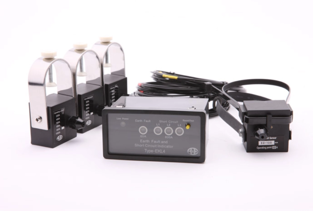
The EKL4 Short-Circuit Grounding Fault Indicator for Cables is one option to evaluate when both detection functions are required. Buyers should confirm its applicable network conditions, electrical ratings, and detailed specifications with the manufacturer.
How Do Accuracy and Anti-Interference Affect Selection?
A fault indicator must distinguish genuine faults from normal electrical disturbances. Its performance depends on the detection method, threshold settings, and network grounding arrangement.
How Does the Grounding Method Affect Ground Fault Detection?
Effectively grounded networks may produce substantial ground-fault currents, while grounding resistors limit current in resistance-grounded systems. Isolated-neutral and resonant-grounded networks can have weaker or more complex fault-current signals because of cable capacitance and neutral displacement. Therefore, the detection method must match the network's grounding arrangement.
Why Should Detection Thresholds Not Be Set Too Low?
A low threshold can help detect weak faults but may trigger false alarms during load fluctuations, transformer energization, or switching operations. Conversely, a threshold that is too high may miss high-resistance ground faults or other low-current faults.
Buyers should compare the detection threshold with expected operating and fault currents. Response delays, reset logic, and interference resistance also matter. Select settings according to network conditions and manufacturer specifications rather than assuming that higher sensitivity always means better performance.
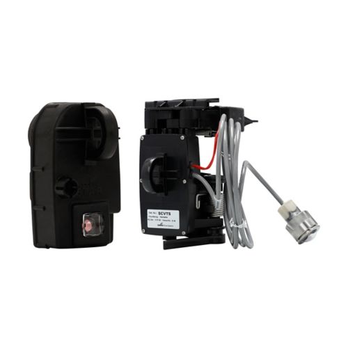
Which Installation, Reset, and Communication Features Matter?
Installation and operating features affect how easily technicians can inspect the network and respond to faults. Buyers should confirm these requirements before finalizing a product specification.
Installation Method and Maintenance Access
Start by checking whether the indicator is designed for cable mounting, panel mounting, or another installation arrangement. The mounting structure must suit the equipment layout and allow technicians to read the indication during routine inspections.
Also consider cable dimensions, available space, sensor arrangement, wiring access, and the need for shutdown during installation. For existing switchgear, verify compatibility with the cabinet design and established maintenance procedures.
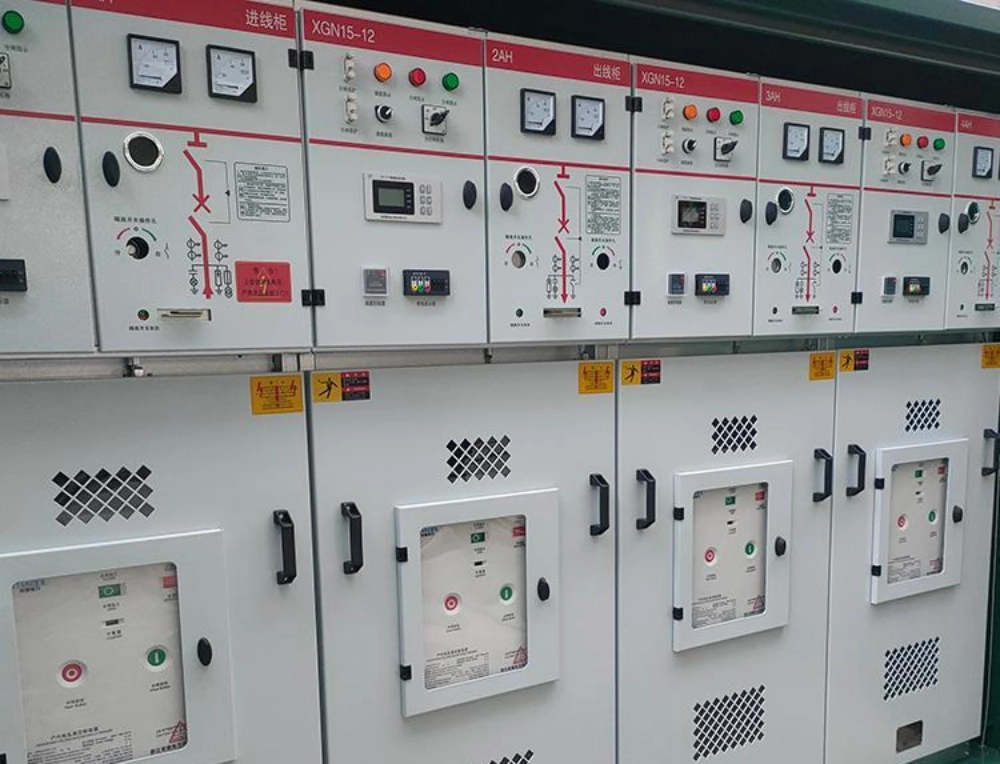
For panel-based applications, the Panel Mounted Paddle Type Short Circuit Fault Indicator may be worth evaluating. Its product page describes fault indication for distribution networks and panel-related applications. Confirm its suitability for the specific installation before selecting it.
Manual, Automatic, and Timed Reset
Fault indicators may use manual reset, automatic reset, or a time-based reset mechanism. The appropriate option depends on inspection procedures and how the network handles fault restoration.
Manual reset allows technicians to inspect an indication before clearing it. Automatic reset can reduce routine intervention when the specified operating conditions are satisfied. Timed reset offers another approach when the project requires a defined reset interval.
However, reset behavior should be coordinated with the protection and maintenance strategy. Confirm the reset conditions, available settings, and response after a fault indication. Do not select a reset method solely because it reduces maintenance effort.
Local Indication or Remote Monitoring
Local indicators allow field technicians to identify abnormal sections during patrols. They may suit smaller networks or installations where regular inspections remain practical.
Remote monitoring can be more useful when the network includes numerous feeder sections, difficult-to-access locations, or centralized distribution automation. Before choosing this option, check whether the device supports the required alarm outputs, communication interfaces, protocols, and auxiliary power arrangements.
Remote communication should be selected according to the project's actual monitoring architecture. Do not assume that every fault indicator supports direct SCADA integration or wireless communication. Confirm the complete signal path and interface requirements with the supplier.
How Should Environmental Conditions and Total Cost Be Evaluated?
Operating conditions can affect product suitability and long-term reliability. Buyers should verify the specified temperature range, humidity limits, enclosure protection, and other environmental requirements against the installation site.
Underground cable chambers, outdoor distribution equipment, and indoor switchgear can present different challenges. Moisture, dust, temperature variation, and limited maintenance access may influence the required product design.
Maintenance requirements also affect long-term costs. Consider battery replacement where applicable, periodic functional checks, spare parts, reset procedures, and technician access. A device with a lower purchase price may create higher operating expenses if it requires frequent intervention or proves difficult to maintain.
Total cost of ownership should therefore include the purchase price, installation, communication infrastructure, maintenance, and expected troubleshooting effort. For projects involving multiple feeders, consistency across product models and replacement parts may also simplify future maintenance.
The best choice balances technical suitability, reliable fault indication, installation requirements, and lifecycle cost. Buyers should compare products against the same specification rather than relying on price alone.
What Should Buyers Check Before Ordering a Cable Fault Indicator?
Before requesting a quotation, prepare a technical checklist that describes the application and required functions. This makes supplier comparisons more meaningful and helps prevent specification gaps.
| Selection factor | Questions to confirm |
|---|---|
| Network conditions | What are the rated voltage, cable type, and network grounding method? |
| Detection functions | Is short-circuit detection, ground-fault detection, or both required? |
| Detection settings | What thresholds, response delays, and reset conditions are needed? |
| Installation | Is cable mounting or panel mounting required? Are there space constraints? |
| Indication and communication | Is local indication sufficient, or is remote monitoring necessary? |
| Environmental conditions | What temperature, humidity, and enclosure protection requirements apply? |
| Documentation | Can the supplier provide applicable drawings, wiring details, and test records? |
| After-sales support | Are technical assistance, spare parts, and warranty terms available? |
Buyers should also verify the manufacturer's experience with comparable applications. Ask for relevant technical documentation and confirm which specifications apply to the proposed model.
For customized projects, clarify the required mounting style, alarm outputs, reset method, and documentation before production. If several devices will be installed across one network, standardizing specifications can simplify procurement and maintenance.
A clear technical request helps suppliers recommend suitable products and reduces the risk of selecting equipment based on incomplete information.
FAQs About Cable Fault Indicator Selection
What Is the Difference Between a Cable Fault Indicator and a Cable Fault Locator?
A cable fault indicator identifies a section where a qualifying electrical fault has occurred. Multiple indicators along a circuit can help technicians narrow down the affected area. A cable fault locator typically uses electrical testing or diagnostic techniques to estimate fault distance or pinpoint the damaged location. The two devices serve complementary purposes. Indicators support faster fault-section identification, while testing equipment can assist with further diagnosis and repair planning.
Can One Cable Fault Indicator Detect Both Short-Circuit and Ground Faults?
Some indicators support both short-circuit and ground-fault detection, but this capability depends on the product design. Buyers should verify the supported detection methods and the electrical conditions under which they operate. Ground-fault detection is particularly dependent on the network grounding arrangement and fault-current characteristics. Before ordering, confirm the device's detection thresholds, applicable network conditions, and test documentation. A combined function should not be assumed to guarantee suitability for every distribution network.
Should I Choose a Local or Remote Cable Fault Indicator?
Choose local indication when technicians can inspect the network efficiently and centralized monitoring is unnecessary. Remote monitoring may be more suitable for extensive distribution networks, difficult-to-access equipment, or projects requiring centralized fault information. Consider the communication protocol, auxiliary power supply, alarm interface, and compatibility with existing monitoring systems. Remote functionality may increase system cost and integration requirements. The decision should reflect maintenance practices, network scale, and operational needs rather than assuming that more communication features always provide better value.
Conclusion
Effective cable fault indicator selection starts with a clear understanding of network conditions and detection requirements. Buyers should evaluate fault types, grounding arrangements, detection thresholds, installation methods, reset behavior, and communication needs.
Environmental suitability, maintenance requirements, and total cost also influence long-term performance. Comparing products against a defined technical specification helps engineers and procurement teams avoid unsuitable choices.
Xinyuan offers a range of earth-fault indicators and related products for evaluation across different applications. Before ordering, confirm the model's technical parameters and compatibility with your electrical system. This approach helps ensure that the selected indicator supports practical fault identification and efficient maintenance.