How To Choose The Right Types Of Earth Fault Indicator?
Select the most reliable types of earth fault indicator for medium voltage grids. Maximize system safety and reduce downtime.
")

Navigating Modern Grid Challenges with Correct Types of Earth Fault Indicator
Modern medium voltage networks require robust protective devices to maintain continuous power flow. Grid operators often deploy specific types of earth fault indicator to locate phase-to-ground faults quickly. These advanced instruments monitor current anomalies and voltage drops across active distribution lines. Rapid detection prevents severe substation damage and reduces costly outages for industrial facilities. Utility companies regularly face challenges from transient faults and permanent insulation breakdowns. Engineers must choose high-quality equipment that matches their network characteristics. Faulted circuits create significant thermal stress on aging utility infrastructure. Standardized sensing units mitigate these risks by triggering local alarms or remote SCADA alerts. Selecting the correct configuration ensures long-term operational safety and grid resilience. High system reliability directly benefits end users by minimizing overall downtime.
Key Technical Parameters of Overhead and Cable Network Sensors
Substation engineers analyze physical grid structures before purchasing any diagnostic equipment. Overhead lines rely on split-core current transformers to detect abnormal electromagnetic field fluctuations. Cable networks require compact sensors that fit tightly around insulated conductors. For instance, operators install a Panel mounted Paddle Type Short circuit Fault Indicator in dense control cabinets. This specific mechanical device utilizes a physical flag to display status changes clearly. The sensor registers current spikes exceeding preset thresholds. Such mechanisms eliminate the need for continuous external power supplies. Modern units utilize robust materials like polycarbonate housing to resist extreme UV radiation. Outdoor components also require high ingress protection ratings to survive severe storms. These strict mechanical standards guarantee decades of service in challenging industrial environments.
How Operational Environments Dictate Different Types of Earth Fault Indicator
Harsh operational climates significantly impact the performance of grid monitoring devices. Coastal zones expose metal components to high salinity, which accelerates corrosive wear. Desert installations must withstand heavy sandstorms and extreme daily temperature shifts. Underground distribution networks face constant moisture ingress and risk periodic flooding. Reliable protective units survive these challenges by utilizing epoxy-resin casting for vital circuitry. Manufacturers design specialized enclosures to prevent dust penetration and water damage. These housing specifications protect delicate microprocessor boards from thermal shock and vibration. Correct hardware protection minimizes false alarms caused by localized environmental disturbances. Smart operators evaluate local weather historical data before choosing specific field devices. Robust engineering standards shield the internal sensors from high electromagnetic interference.
Essential Selection Metrics for Industrial Power Distribution Systems
Selecting network hardware requires a deep analysis of specific electrical parameters. Electrical utilities must calculate minimum and maximum fault currents for each branch. This baseline data determines the required sensitivity of the detection units. Engineers also verify the automatic reset settings of each device. Some networks prefer time-based resets, while others require voltage restoration triggers. Power supply options also influence long-term maintenance costs significantly. Lithium batteries offer long service life but require periodic physical replacement. Dual-powered models harvest current directly from the line during normal operation. This feature minimizes energy drain on the backup battery system. System operators evaluate these criteria to ensure seamless integration with existing safety protocols.
- Minimum tripping current threshold starting from ten amperes up to one hundred amperes
- Adjustable physical response delay settings ranging from forty milliseconds to three hundred milliseconds
- Mechanical reset, automatic timer reset, or remote SCADA signal reset mechanisms
- Dual-power configuration utilizing both primary line current harvesting and back-up lithium cells
- Modbus RTU or DNP3 protocol compatibility for seamless integration with existing SCADA networks
A Deep Analysis of Vital Selection Metrics for Grid Reliability
The listed technical parameters directly dictate how successfully a utility operates its medium voltage infrastructure. Tripping threshold adjustment prevents false alarms during temporary inrush currents. System operators configure these settings based on the load profile of each substation feeder. Furthermore, remote reset capabilities save hours of manual field labor after transient faults clear. Technicians avoid driving to remote physical sites just to reset tripped mechanical indicators.

Selecting specific types of earth fault indicator with dual-power options lowers overall operating expenses. Current-harvesting technology ensures continuous monitoring even during prolonged backup battery depletion. Modern control centers receive instant binary signals via Modbus protocols to map outage locations. This immediate data flow speeds up network restoration times by guiding maintenance crews directly to damaged cable segments.
Performance Comparison of Core Detection Technologies
Modern grid protection relies on two primary methodologies for identifying ground faults. Current-only detection units monitor zero-sequence current balance using simple ring-type transformers. This classic approach provides cost-effective monitoring for simple radial networks. In contrast, directional detection units analyze both current phases and voltage vectors simultaneously. This dual-sensing capability proves essential for complex closed-loop distribution grids. Engineers select directional models to prevent false tripping from back-fed currents. These units calculate phase angle shifts to identify the exact location of the earth fault. The choice between these physical designs depends on system grounding characteristics and substation configurations. Solidly grounded networks require different sensitivity ranges than high-impedance systems. Utility planning teams compare these technical aspects before upgrading their physical infrastructure.
| Technical Specification | Current-Only Sensing | Directional Sensing |
|---|---|---|
| Primary Measured Value | Zero-sequence current (Io) | Current (Io) & Voltage (Uo) |
| Grid Suitability | Simple radial systems | Closed-loop or parallel lines |
| Fault Direction Tripping | Non-directional | Highly directional (Forward/Reverse) |
| Sensitivity Range | 10A to 100A | 1A to 50A |
Interpreting Technical Performance Metrics for Substation Deployment
The tabulated data highlights how different technical designs serve specific roles within medium voltage substations. Current-only sensing devices offer extreme reliability in basic radial distribution feeders. Their mechanical simplicity ensures long service life with minimal physical calibration. However, complex parallel networks demand directional units that prevent incorrect tripping on healthy lines. Using advanced directional types of earth fault indicator avoids costly power disruptions caused by capacitive discharge. These smart devices verify phase angle differences to isolate the exact faulted cable section. This diagnostic capability reduces maintenance cycle duration and improves utility reliability metrics. Network designers integrate these parameters into substation automation blueprints. Selecting the correct technical profile prevents unnecessary utility equipment stress.
Comparing Mechanical Flags versus Electronic Communication Interfaces
Distribution automation relies on clear, rapid signal propagation to minimize diagnostic delays. Traditional equipment displays fault status using physical, high-visibility mechanical flags. Field crews drive along the distribution route to spot these visual targets manually. Modern networks utilize electronic interfaces that transmit digital alarms directly to SCADA systems. For underground circuits, operators deploy a Cable Type Short Circuit Grounding Flash Fault Indicator to monitor critical junctions. These digital units send real-time coordinates over cellular or radio frequencies. Electronic reporting eliminates visual inspection delays during severe weather events or nighttime outages. Engineers compare physical visibility against digital integration capability when selecting equipment. This choice impacts both initial capital expenses and long-term utility operating budgets. The selected system must align with the existing grid communication standard.
| Feature Profile | Mechanical Indicator | Electronic Digital Indicator |
|---|---|---|
| Status Visualization | Physical red/yellow paddle flag | Flashing LED & binary dry contacts |
| Communication Channel | Visual line-of-sight only | Modbus, GPRS, 4G, or NB-IoT protocols |
| Operational Power | Self-powered mechanical spring | Lithium battery or line energy harvesting |
| Initial Capital Cost | Low cost per unit | Moderate to high investment |
Analyzing Transmission Features for Distribution Management Systems
Evaluating the comparative data reveals clear operational differences between physical flags and electronic reporting interfaces. Mechanical flags function excellently on visible overhead lines where utility crews possess clear line-of-sight. Their low purchase cost allows dense deployment across rural radial circuits. However, modern smart grids benefit heavily from electronic types of earth fault indicator with cellular connectivity. These smart units transmit urgent alert messages to centralized management systems within seconds of fault detection. Operators map out precise trouble zones immediately without sending patrol vehicles into the field. This capability reduces average service restoration time and boosts customer satisfaction scores. Utility managers choose the optimal transmission style based on local physical access and budget constraints. Proper planning ensures the protection devices operate reliably under extreme conditions.
FAQ
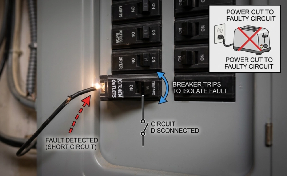
What is the primary function of a faulted circuit indicator in MV systems?
Faulted circuit indicators isolate ground anomalies quickly within medium voltage networks. These physical units detect abnormal current spikes during earth fault events. They display a visual flag or transmit a digital warning signal immediately.This rapid reporting helps field crews locate damaged grid segments without manual trail-and-error switching.

Why is remote communication critical for modern utility networks?
Modern distribution grids span thousands of miles of rural and urban territory. Manual physical inspections consume massive labor hours during emergency storm outages. Remote communication interfaces allow advanced types of earth fault indicator to report events instantly. These smart devices transmit fault coordinates directly to utility control systems. Control rooms receive real-time updates via GPRS or cellular protocols. This immediate alert capability allows engineers to dispatch crews to exact fault locations immediately. Consequently, utility companies experience fewer service disruptions and save valuable operational maintenance budgets. This continuous real-time data transmission forms the core foundation of modern self-healing smart grids. These remote units secure modern infrastructure.
Consequently, utilities reduce the average duration of power outages significantly. Implementing these protective units improves overall grid reliability indices like SAIDI and SAIFI. Operators isolate damaged cable branches while maintaining continuous electricity flow to healthy network areas. This proactive targeted response minimizes utility equipment degradation and prevents secondary damage to expensive substation transformers. These devices shield fragile equipment.
How do dual-sensing units distinguish between transient and permanent faults?
Dual-sensing protective units monitor both zero-sequence current levels and network voltage phases simultaneously. Transient faults occur briefly during windstorms or tree contact, then disappear rapidly. Permanent faults remain until repair crews repair the physical line damage. The monitoring device detects transient events when current spikes briefly but voltage recovers instantly. This internal microchip registers a temporary alert but avoids triggering a permanent fault status. If the voltage remains absent after the current spike, the system identifies a permanent fault. This logic triggers a permanent visual indicator or a SCADA alarm. Advanced automated diagnostic algorithms eliminate false alarms and streamline physical utility maintenance schedules.