NEWS

  1. Home
  2. Earth-Fault Indicator
  3. How To Perform An Earth Fault Indicator Reset?
Why Choose Xinyuan Electric

≡ Categories

VDIS

Earth-Fault Indicator

Indoor Electromagnetic Locks

Temperature & Humidity Controller

Cabinet Light

Please enable JavaScript in your browser to complete this form.

How Can We Help You Today?

How To Perform An Earth Fault Indicator Reset?

Jun 10, 2026

How To Perform An Earth Fault Indicator Reset?

Execute an earth fault indicator reset safely to maintain medium voltage network stability and secure critical distribution assets.

Ekl4 Earth Fault Indicator Short Circuit Indicator
How To Perform An Earth Fault Indicator Reset

Grid operators maintain electrical reliability through advanced monitoring equipment. Medium voltage networks require rapid isolation of abnormal currents. Technicians deploy the Cable Type Short Circuit Grounding Flash Fault Indicator to locate faults quickly. This specialized device signals ground disturbances along buried lines. After clearing a fault, operators must execute an earth fault indicator reset to restore normal operation. Modern systems rely on prompt restoration to prevent secondary outages. Delayed actions can lead to incorrect telemetry reports at the control center. Maintenance crews follow strict utility safety rules during physical inspection. Proper clearing procedures ensure long-term reliability of local substations. Industry professionals track system telemetry to ensure continuous energy delivery. Efficient recovery protocols protect expensive distribution transformers from damage.

Primary Electrical Triggers for Grid Device Activation

Current imbalances trigger diagnostic equipment during an active grid fault. Zero-sequence sensors continuously monitor the vector sum of three-phase currents. Solid grounding issues cause a sudden spike in neutral current levels. This excess current induces a magnetic field within the sensing coil. Electromagnetic forces then release a mechanical flag or trip a relay. Standard thresholds often range from ten to one hundred amperes. Utility engineers pre-program these trigger levels based on network impedance. High impedance faults require highly sensitive detection algorithms. Modern sensors utilize precise microprocessor chips to analyze wave shapes. Real-time digital filtering removes transient harmonics from the signal. Accurate calibration prevents nuisance tripping from normal load variations. Consequently, the monitoring device only captures genuine insulation failures. Rapid detection limits cumulative thermal stress on insulation materials.

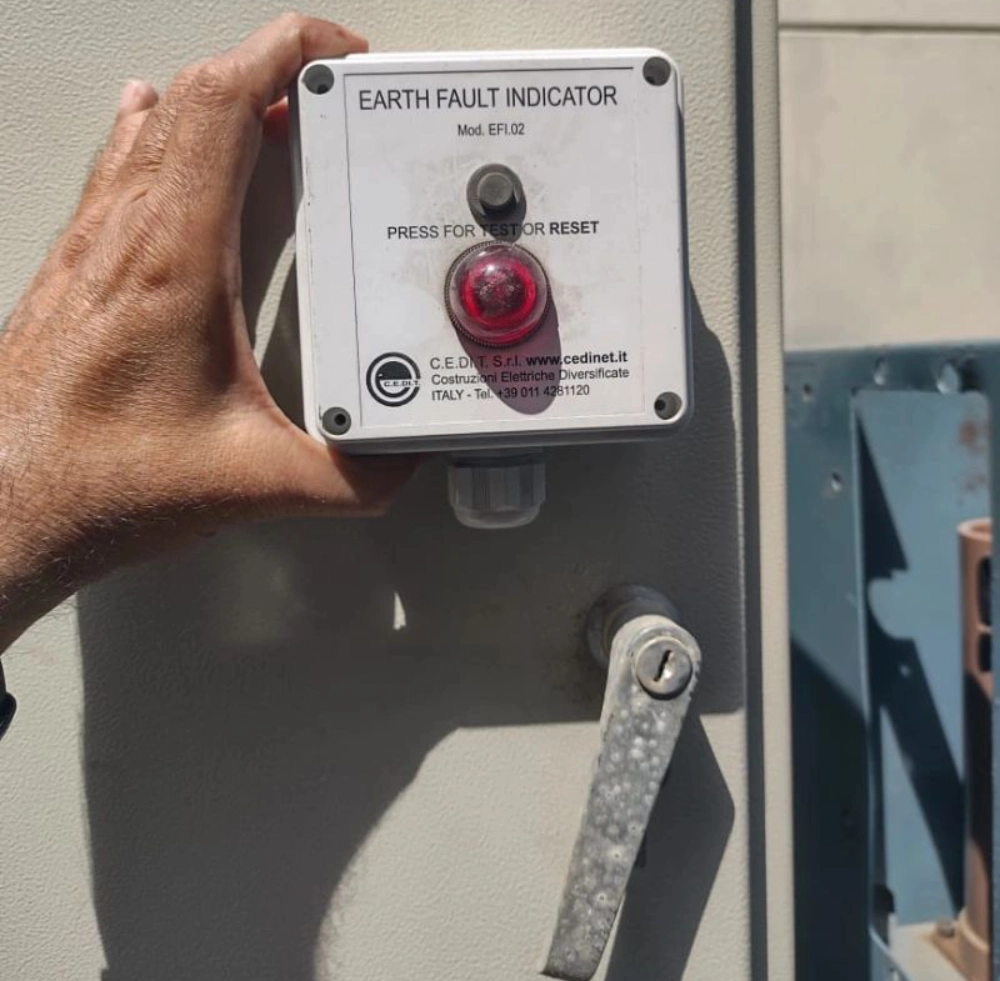
Manual Restoration Protocols for Local Distribution Networks

Substations often utilize traditional hardware for immediate visual verification. Field operators inspect physical displays during routine maintenance walks. The Panel mounted Paddle Type Short circuit Fault Indicator provides clear physical signals. A bright mechanical flag drops when a fault occurs. Technicians must physically visit the location to clear this indication. They press a heavy-duty spring button on the front plate. Alternatively, some models require a magnetic wand for local clearance. This manual action resets the internal mechanism to its neutral state. Local inspections allow crews to verify physical equipment condition directly. Operators look for signs of thermal degradation or moisture penetration. Addressing physical wear immediately prevents future hardware failures. Manual procedures remain a highly reliable fallback method for utilities. Verified clearances ensure subsequent diagnostic signals remain highly accurate.

Automating System Recovery via Remote Protocols

Modern power grids favor automated solutions to reduce field crew deployment. Intelligent electronic devices perform an automatic earth fault indicator reset without human presence. Internal current transformers detect the return of normal operating current. Once current exceeds a predefined threshold, the system triggers clearance. Additionally, voltage sensors can initiate clearance when primary power returns. Remote commands offer another efficient pathway for control room dispatchers. Operators send binary reset signals directly through SCADA communication networks. These networks often transmit data via IEC 60870-5-104 protocols. Fiber-optic links guarantee rapid signal delivery to distant substations. Such automation reduces outage duration metrics significantly. Distant facilities regain monitoring capability within seconds after fault clearance. Decentralized management software tracks every command for audit purposes. Efficient remote operations lower overall utility maintenance costs.

Reset Method Primary Trigger Source Execution Speed Auxiliary Power Need
Manual Button Physical operator input Minutes to hours None (Mechanical)
Automatic Voltage Primary current restoration 10 to 30 seconds Low power capacitor
Remote SCADA Software control signal Under 2 seconds Continuous DC supply

Analyzing Operational Recovery Metrics of Grid Indicators

Grid performance metrics highlight distinct variations among restoration methods. Manual intervention demands substantial travel time for field operators. Consequently, physical actions yield the slowest restoration response speeds. Local mechanical setups do bypass any need for auxiliary power. Automatic systems instead monitor voltage levels on the distribution lines. They utilize small capacitive charges to trigger internal bistable relays. Remote digital options provide the most rapid response for operators. Central dispatchers execute these commands via secure communications links. This method requires a steady external direct current power supply. Reliable backup batteries sustain these communication circuits during blackouts. Selecting the correct method depends heavily on substation connectivity. Utility engineers balance physical deployment constraints against automation budgets. Comprehensive grid designs often combine multiple restoration options.

Sensor Type Measurement Range Accuracy Class Standard Compliance
Rogowski Coil 10A to 5000A Class 1.0 IEC 61869-10
Split-Core CT 5A to 1000A Class 3.0 IEC 61869-2
Epoxy-Cast CT 1A to 600A Class 0.5 IEC 60044-1

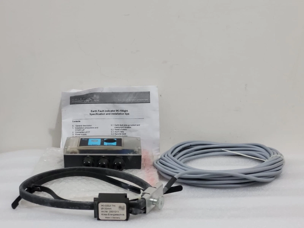
Interpreting Mounting Configurations and Sensor Designs

Sensor selection directly influences data accuracy in electrical distribution systems. Rogowski coils deliver broad measurement ranges for high current applications. These lightweight sensors perform beautifully during intense transient events. Their non-magnetic core design prevents saturation under heavy fault currents. Alternatively, split-core transformers offer easy retrofitting on existing cables. Technicians install these split devices without cutting critical power lines. Cast epoxy variants provide maximum protection against harsh environmental elements. This design delivers excellent measurement accuracy for sensitive protection relays. Each sensor type complies with specific international IEC standards. Compliance ensures equipment safety during massive physical system faults. System designers must evaluate these electrical metrics before installation. Correct engineering choices prevent premature sensor degradation in the field. Proper hardware integration guarantees precise fault localization for utility crews.

  • Sensing Transformer: Measures current fluctuations and detects earth faults.
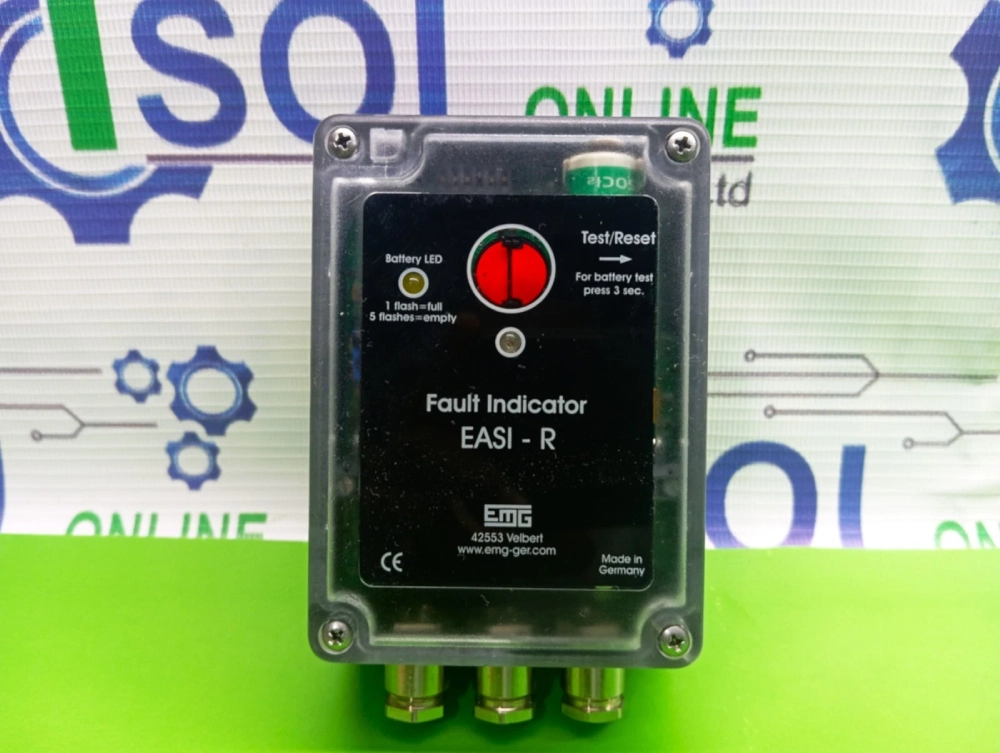
  • Bistable Display Flag: Shows local physical fault signals without constant power.
  • Lithium Battery Pack: Sustains local monitoring circuits for over ten years.
  • Fiber-Optic Cable: Transmits isolated digital telemetry safely to SCADA modems.
  • Microcontroller Board: Decodes sensor inputs and executes reset commands.

Deconstructing Core Hardware Modules and Functional Circuits

Each discrete hardware block plays a critical role in system safety. Sensing transformers continuously translate high primary currents into manageable values. 

How To Perform An Earth Fault Indicator Reset?

This scaling action allows delicate microprocessors to process data safely. Mechanical display flags hold their physical state with zero power. Internal lithium batteries specifically power the communications card during outages. These batteries guarantee continuous operation for more than a decade. Fiber-optic links shield weak digital logic boards from high voltage surges. Such optical isolation prevents component damage during lightning strikes. Central microcontrollers analyze analog waves and control the display flags. Processor chips also run software algorithms to detect faults quickly. High quality manufacturing processes ensure these components survive outdoors. Robust enclosures shield delicate electronics from extreme temperature variations. Consequently, the complete assembly delivers reliable performance under stress.

Essential Tools For An Earth Fault Indicator Reset

Field operators require proper instrumentation to maintain distribution networks. Safety remains the highest priority during physical substation tasks. Technicians carry insulated hot sticks to handle high voltage gear. These fiberglass poles isolate the worker from active electrical lines. Crew members must perform an earth fault indicator reset safely. They use specialized magnetic wands for non-contact clearance procedures. This tool interacts with internal reed switches inside the enclosure. Digital multi-meters help verify physical power flow through local circuits. Operators also carry personal protective suits rated for arc flashes. Such gear prevents severe injuries from unexpected electrical faults. Handheld calibration instruments allow rapid field testing of sensors. Maintenance vehicles stock these tools for immediate emergency dispatches. Having correct tools ensures efficient work and minimizes grid downtime.

Standard Testing Protocols for Operational Validation

Periodic validation guarantees system readiness before actual faults occur. Commissioning engineers perform primary injection testing on new installations. Experts inject simulated high currents directly into primary sensors. This test confirms the precise response threshold of each unit. Next, operators verify the telemetry links back to SCADA. Digital feedback loops must report correct alarm states instantly. Secondary validation involves checking mechanical parts for smooth action. Technicians physically inspect springs and visual display flag alignment. Incorrect settings during installation can compromise entire grid systems. Therefore, engineers sign off on formal compliance sheets immediately. These documents confirm adherence to national safety regulations. Regular audits maintain the high integrity of utility network structures. Detailed logs provide invaluable data for subsequent root cause analysis. Safe operation relies directly on these methodical testing steps.

Preventative Maintenance Routines for Distribution Systems

Proactive maintenance plans extend the lifespan of critical grid hardware. Technical teams schedule seasonal inspections of pole-mounted outdoor enclosures. Environmental factors like salt spray degrade physical contacts over time. Clean connections prevent high resistance path development inside terminals. Crews also verify the local earth fault indicator reset function periodically. Testing ensures that internal solenoids actuate without mechanical sticking. Battery voltage measurements help predict potential failures before winter. Cold weather reduces cell capacity and slows mechanical responses. Replacing old cells guarantees reliable local flag operation during outages. Additionally, technicians apply silicone grease to protect rubber door seals. Waterproof housings keep delicate electronic circuit boards completely dry. Such routine physical tasks dramatically reduce unscheduled emergency deployments. Ultimately, stable networks rely on these small preventative steps.

Earth Fault Indicator Reset

FAQ

How does automatic reset function after voltage restoration?

Automatic clearance depends on primary circuit conditions returning to normal. Internal current transformers sense the flow of nominal load currents. Once current exceeds a pre-set value, the sensor generates energy. This small power surge feeds into a low-voltage capacitor. The capacitor then discharges its stored energy into a solenoid. Such electromagnetic pulse initiates the earth fault indicator reset action. Consequently, the mechanical flag moves back to its hidden state. Digital communication cards transmit a cleared status report to SCADA. Normal monitoring services resume instantly without manual field operator intervention. Reliable automatic recovery streamlines distribution grid operations during stormy seasons.

What causes a manual reset mechanism to fail?

Physical wear often leads to mechanical failure in outdoor environments. Corrosion degrades local pushbuttons after years of direct weather exposure. Hardened spring grease prevents internal levers from sliding back smoothly. Moisture entry can also cause electrical shorts within reset solenoid coils. Additionally, dead lithium backup batteries prevent electromagnetic release functions entirely. Vibrations from nearby heavy traffic sometimes dislodge critical internal linkages. Regular physical inspections help identify these issues before they cause trouble. Technicians must clean contacts and replace worn components to restore functionality. Clean housings prevent dirt buildup around external mechanical actuator shafts. Proper field care maintains reliable local operation over long lifespans.

Can remote SCADA commands reset all indicator types?

Remote clearing requires specific smart components within the system. Basic mechanical indicators lack communication modules for receiving digital signals. These older devices only support physical manual restoration on site. Modern intelligent electronic devices feature integrated RS485 or fiber-optic ports. Such electronic units accept standard binary control signals from SCADA master stations. Utility engineers specify these smart features during substation upgrade projects. Compatibility tables help ensure seamless integration across different hardware brands. Network protocols must match exactly to execute commands successfully. Therefore, operators verify system design before planning remote control operations. Smart grids rely on these connected devices to maintain safe distribution.