
How to Read a Cable Fault Indicator Wiring Diagram
Read a cable fault indicator wiring diagram by model. Check sensor channels, earth paths, reset contacts, alarm relays, and RS485 terminals.
Follow the Sensor and Interface Paths
A cable fault indicator wiring diagram shows how the sensing channels and external interfaces connect to the display unit. Start with the complete model suffix and its assigned drawing. Confirm the rear viewing direction before locating terminals. Next, trace each phase sensor and the earth-fault sensor to their labeled inputs. Identify remote reset, alarm contacts, and communication separately by their documented functions. Check any required supply against the exact variant. Finish by comparing the drawing with the installed conductor and screen arrangement. Record those assignments before the qualified team begins connection or testing.
Match the Cable Fault Indicator Wiring Diagram to the Model
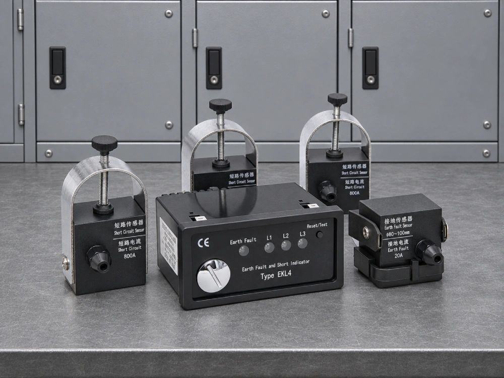
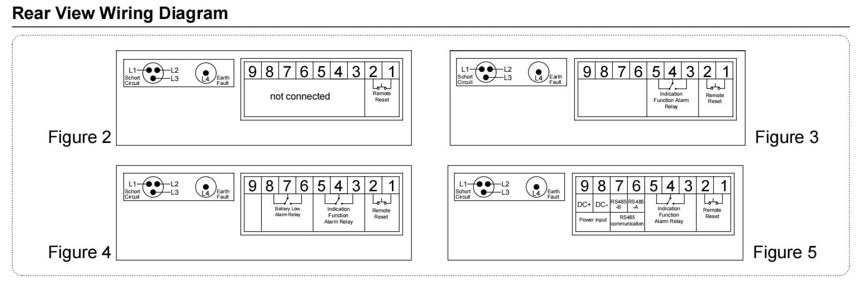
The EKL4 technical sheet assigns separate rear views to its four listed versions. EKL4-4 uses Figure 2, while EKL4-3 uses Figure 3. The table assigns Figure 4 to EKL4-5 and Figure 5 to EKL4-6. Compare the nameplate with that table before using a terminal schedule. A shared housing does little to establish which external functions a particular unit provides. Check the supplied diagram revision and actual rear markings together. Include the model suffix on every connection record so later maintenance can identify the applicable circuit.
Rear-view references in the EKL4 technical sheet
| Version | Figure | External functions to identify |
|---|---|---|
| EKL4-4 | 2 | Remote reset and sensor channels |
| EKL4-3 | 3 | Remote reset, indication alarm relay, and sensor channels |
| EKL4-5 | 4 | Remote reset, indication alarm relay, low-battery alarm relay, and sensor channels |
| EKL4-6 | 5 | Remote reset, indication alarm relay, RS485, power input, and sensor channels |
Keep Phase and Earth-Fault Channels Identifiable
The rear views label the short-circuit channels L1, L2, and L3, with a separate L4 earth-fault input. Trace the actual feeder phase and its sensor identifier through to the matching display channel. A crossed sensor connection can associate a valid event with the wrong phase label. Identify the earth sensor separately and verify its specified connection method. Keep the supplied sensor type and cable requirements with the assembly record. For a replacement, compare the original sensor specifications with the proposed unit. Connector fit alone provides insufficient evidence of electrical compatibility between the sensor and display.
Read Reset, Alarm, Supply, and Communication Interfaces
Figures 2–5 place remote reset at terminals 1 and 2. Identify the reset input requirements before selecting the external device. The relay groups vary by version, so read each contact symbol against the supplied terminal schedule. Confirm its common terminal, switched states, and load rating before connection. Figure 5 additionally marks 9/8 as DC+/DC− and 7/6 as RS485-B/RS485-A. Obtain the specified supply, protocol, address, and bus installation requirements for that version. Verify the normal, alarm, and reset responses through the complete monitoring path. For an integrated voltage-presence and grounding-fault indicator, request its own connection documents before considering substitution. Record every accepted interface assignment on the cabinet drawing.
Check Which Conductors Pass Through the Earth Sensor
The earth-fault sensing arrangement determines which currents contribute to the residual measurement. For a conventional three-phase summation arrangement, the sensor surrounds all three phase conductors at the specified position. Cable screens and their earth leads also influence the current paths at that location. Follow the approved installation drawing for the exact screened cable and sensor arrangement. A return path passing through the sensing window can cancel part of the signal the design intends to measure. Record the sensor position relative to the termination and screen connections. Have the cabinet engineer verify that geometry before commissioning.
What Should a Cable Fault Indicator Wiring Diagram Check Include?
Create a commissioning sheet that lists each sensor channel and every fitted external function. Qualified staff should verify installation and connections under the cabinet's approved safe working procedure. Use the manufacturer's test method to confirm the phase association and earth-fault response. Check local indication against relay alarms or communication points where available. Include remote reset and the specified battery supervision functions in the test. A front test button may exercise only part of the complete sensing path. Confirm its coverage from the instructions and document any separate sensor tests needed for acceptance.
Frequently Asked Questions
Can I use a wiring diagram from another EKL4 version?
Use the diagram assigned to the exact supplied version. The official table associates different suffixes with different alarm, battery, and communication functions. A terminal position that serves an interface on one version may have another assignment elsewhere. Compare the complete model code, rear markings, and diagram revision before approving a replacement. If the supplied documents conflict, ask for a corrected terminal schedule before connection. Update the cabinet drawing when an accepted substitution changes the external interfaces. Retain the approved version with the maintenance records for subsequent work.
Why can the lamps test correctly while earth faults remain undetected?
A front test may check the display electronics without proving the complete installation and sensing path. Confirm what the test actually exercises in the supplied instructions. Qualified staff should then inspect sensor selection, channel assignment, pickup settings, and the conductor arrangement through the sensing window. Include cable screen earth paths in that review. Compare the actual installation with the manufacturer's approved geometry and test procedure. Record the expected earth-fault response and observed result. Those checks help distinguish a working display from an installation that correctly detects the intended residual current.
What information should I provide for a wiring review?
Send the complete model code, rear connection photo, and the applicable product diagram revision. Include the cabinet schematic, sensor identifiers, cable construction, and termination arrangement. Show where the earth sensor sits relative to screen connections and earth conductors. List the required alarm points, reset function, and any communication interface. For external circuits, provide the intended supply and monitoring input requirements. Ask the supplier to confirm the terminal schedule and compatible sensor assembly. Record the accepted configuration on the cabinet drawing so installers and commissioning staff use the same reference.