
How To Select An Earth Fault Indicator For RMU
Choose an earth fault indicator for RMU with reliable detection, suitable sensitivity, grounding compatibility, and easy installation.
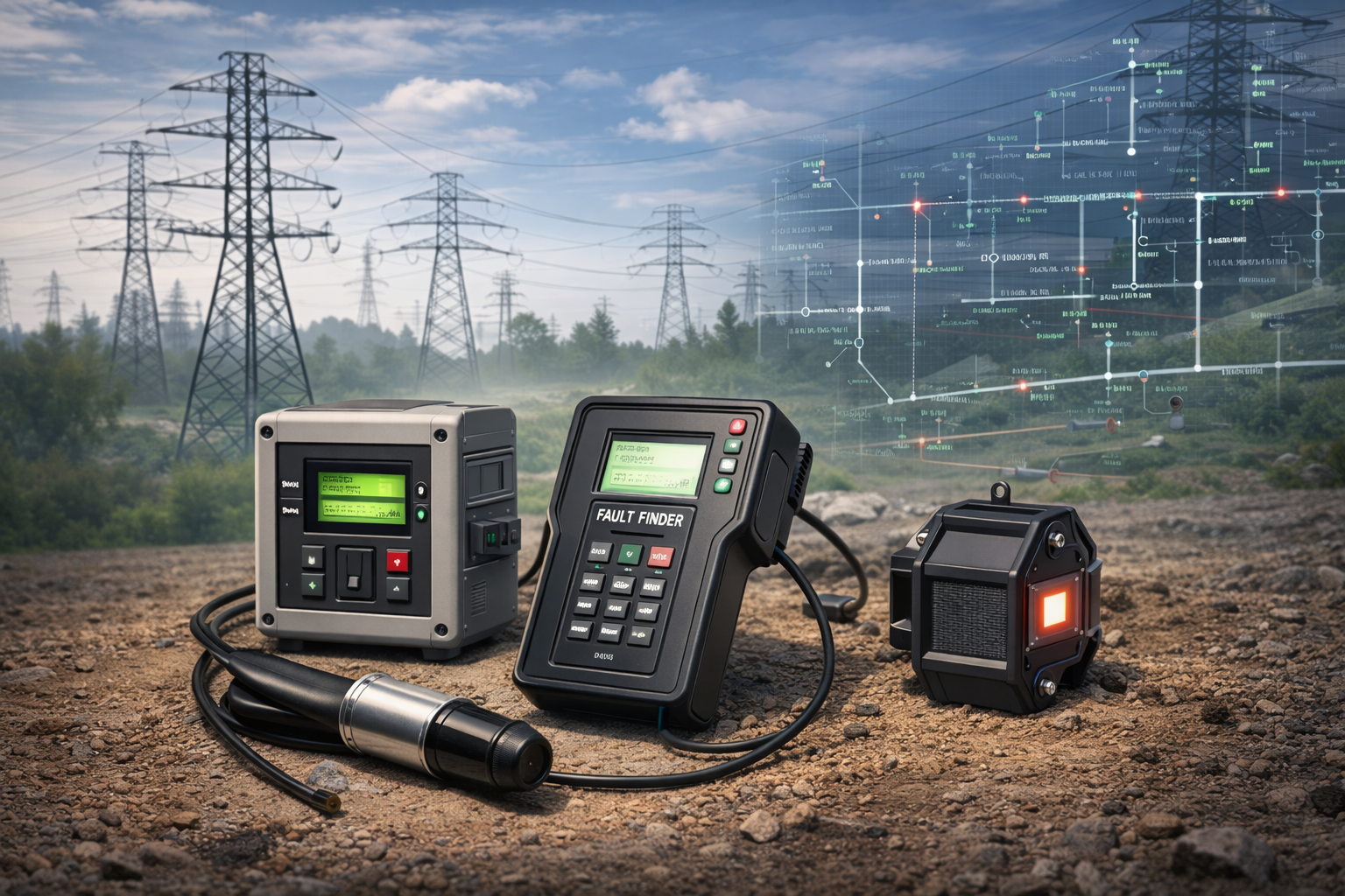
An earth fault indicator for RMU applications helps maintenance teams identify faulty cable sections in medium-voltage distribution networks. Ring Main Units (RMUs) connect multiple feeders and support reliable power distribution. When an earth fault occurs, locating the affected section quickly can reduce inspection time and help restore service efficiently.
However, selecting a suitable indicator requires more than checking its rated voltage or physical dimensions. Engineers must consider the network grounding method, detection sensitivity, sensor configuration, and monitoring requirements. These factors determine whether the device can identify relevant faults under actual operating conditions. The following sections explain the main selection criteria and practical considerations for RMU installations.
How Does an Earth Fault Indicator Work in an RMU?
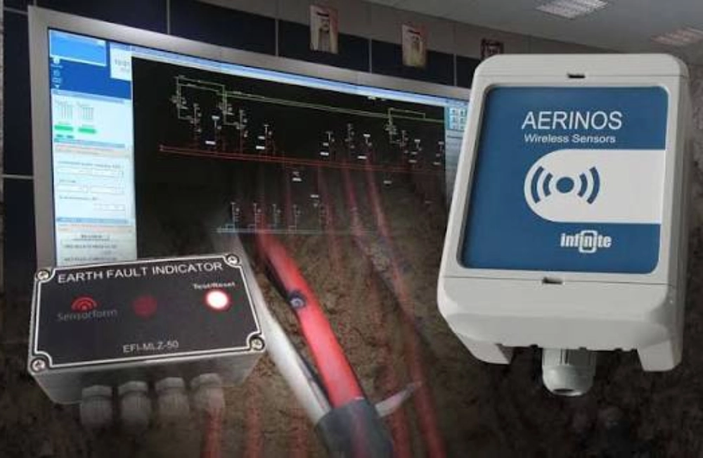
An earth fault indicator monitors electrical conditions and signals when its detection criteria identify a possible ground fault. In an RMU, the device helps maintenance personnel narrow the search to the affected feeder or cable section. Depending on its design, it may provide a visual flag, LED indication, relay output, or remote alarm signal.
Many indicators use current sensors to detect electrical conditions associated with earth faults. A common approach measures residual current, which can become nonzero when phase currents no longer balance. The indicator evaluates the measured signal against configured thresholds and activates an alarm when the required conditions are satisfied.
Earth fault indicators do not normally replace protection relays or circuit breakers. Instead, they support fault location and maintenance decisions. Their effectiveness depends on the sensing method, network characteristics, and correct configuration.
Earth faults and short circuits also require different detection considerations. An earth fault involves an unintended current path to earth or grounded conductive parts. A short circuit may occur between phases or between a phase and earth. Some indicators support both functions, but buyers should verify their separate detection ranges and operating logic.
What Factors Affect Earth Fault Indicator for RMU Selection?
The network grounding method is one of the most important selection factors. Directly grounded and resistance-grounded networks can produce different earth fault current levels. Isolated-neutral and resonant-grounded networks may produce much smaller fault currents, depending on network capacitance and grounding conditions.
Consequently, an indicator suitable for one network may not detect faults reliably in another. Engineers should confirm the expected fault current, minimum detectable signal, and compatibility with the network's grounding arrangement. Sensitive applications may require specialized detection methods rather than conventional current thresholds alone.
The following parameters should be reviewed before selecting an earth fault indicator for RMU installations.
| Selection parameter | Key considerations |
|---|---|
| Detection sensitivity | Minimum detectable earth fault current |
| Operating threshold | Adjustable range and protection coordination |
| Sensor configuration | Sensor type, dimensions, position, and wiring |
| Reset function | Manual, automatic, or remote reset |
| Alarm output | Relay contacts and electrical ratings |
| Power supply | Battery requirements or external auxiliary power |
| Environmental protection | Operating temperature and enclosure protection |
| RMU compatibility | Mounting space, cable arrangement, and interface requirements |
Sensor compatibility deserves particular attention. Incorrect sensor positioning or unsuitable wiring can affect measurement accuracy. Buyers should check the manufacturer's installation drawings and confirm that the sensing arrangement matches the RMU's cable configuration.
Threshold settings also require careful consideration. A threshold that is too high may miss relevant faults, while an excessively low setting may cause unwanted indications. Engineers should determine appropriate settings using network calculations, protection requirements, sensor characteristics, and manufacturer recommendations.
How to Install and Test an Earth Fault Indicator for RMU
Correct installation helps ensure reliable detection and clear fault indication. Before mounting the device, technicians should review the manufacturer's drawings, wiring diagrams, and sensor instructions. They should verify the intended sensor position, terminal connections, and compatibility with the installed cables.
Commissioning should confirm that the indicator responds correctly to approved test conditions. Technicians should verify the configured thresholds, local indication, reset function, and available alarm outputs. Testing must follow the manufacturer's procedures and site safety requirements. Creating an uncontrolled earth fault on energized equipment is not an acceptable test method.
Local indication may be sufficient for RMUs that rely on field personnel for fault inspection. However, distribution networks with centralized monitoring may require remote alarm transmission through an RTU or SCADA system. Some indicators provide relay outputs or communication interfaces for this purpose, while others only offer local indication.
When SCADA integration is required, buyers should confirm that the selected indicator provides compatible outputs. The commissioning team should also verify that remote alarms correspond to the actual indicator states. SCADA connectivity is an optional feature for many applications, not a universal requirement for every earth fault indicator.
Common operational problems include false indications, missed detections, failed resets, and missing remote alarms. Troubleshooting should begin with the approved threshold settings, sensor installation, wiring, power supply, and signal configuration. Maintenance schedules should follow manufacturer recommendations and applicable site requirements.
What Should Buyers Check When Purchasing an Earth Fault Indicator for RMU?
A clear technical specification helps buyers avoid compatibility problems and unnecessary installation changes. Before requesting a quotation, engineers should prepare the RMU configuration, network grounding method, expected earth fault current, and required indication functions.
The following checklist can support supplier communication:
- Network requirements: Confirm rated voltage, grounding arrangement, expected fault current, and protection settings.
- Installation conditions: Provide the RMU model, cable arrangement, mounting dimensions, and relevant drawings.
- Detection performance: Specify the required sensitivity, operating thresholds, and any specialized detection needs.
- Functional requirements: Identify local indication, reset options, relay outputs, and remote monitoring requirements.
- Power and environment: Confirm auxiliary power availability, battery requirements, operating temperature, and enclosure protection.
- Technical documentation: Request data sheets, wiring diagrams, dimensional drawings, and relevant test documentation.
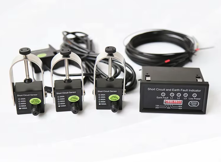
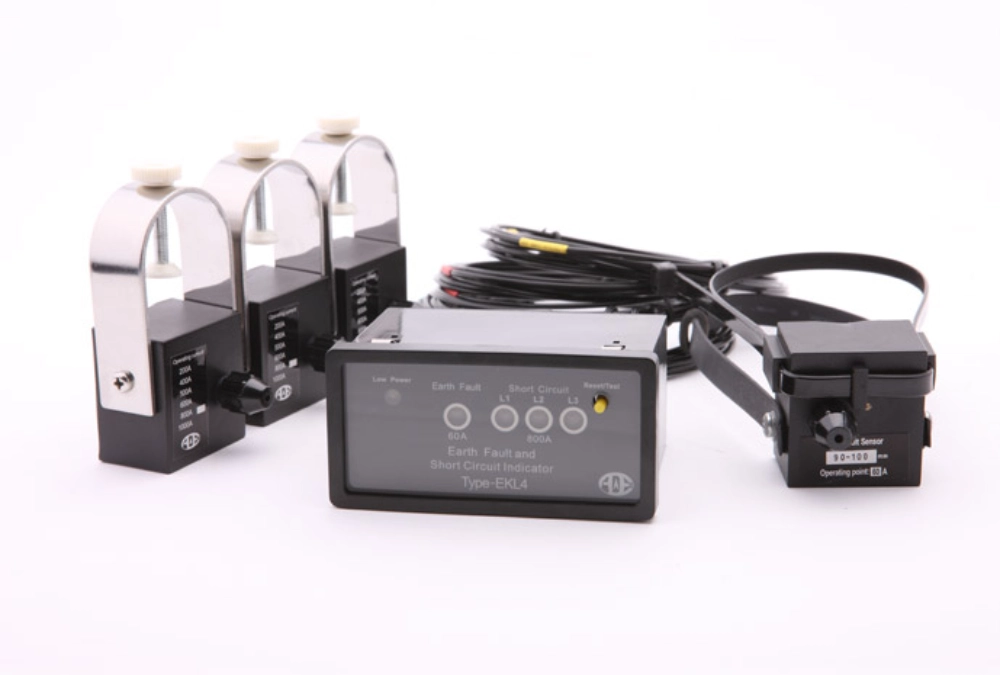
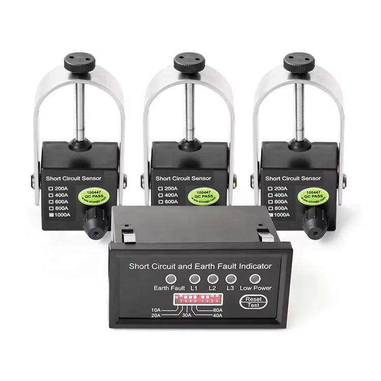
For example, the EKL4 Short-Circuit Grounding Fault Indicator for Cables is listed for applications including RMUs and medium-voltage distribution lines. Its published features include adjustable short-circuit and grounding-current thresholds, automatic reset, and alarm relay output.
Buyers should compare these functions with their actual project requirements before confirming suitability. Specialized grounding arrangements, remote monitoring needs, and nonstandard installation conditions may require additional technical verification. Requesting written confirmation from the supplier can help clarify compatibility before ordering.
Frequently Asked Questions
Can an Earth Fault Indicator Be Used in Any RMU?
No. Compatibility depends on the network grounding method, fault current, sensing principle, and RMU installation conditions. Some indicators support only specified current ranges or sensor arrangements. Others provide combined short-circuit and earth fault detection. Engineers should verify minimum detectable current, threshold settings, installation requirements, and output functions before selecting a model. Manufacturer confirmation is particularly important for isolated-neutral and resonant-grounded networks, where conventional current thresholds may not detect every relevant fault.
Does an RMU Earth Fault Indicator Need SCADA?
No. A local indicator can provide useful fault information without a SCADA connection. Remote monitoring is beneficial when operators need centralized alarms or automated distribution management. In these applications, buyers should confirm the available relay outputs or communication interfaces and their compatibility with the RTU or controller. They should also define the required signals and commissioning tests before ordering the equipment.
How Often Should an RMU Earth Fault Indicator Be Tested?
The testing interval should follow manufacturer instructions, site maintenance procedures, and applicable electrical requirements. Inspections may include checking the device condition, verifying configuration, examining sensor connections, and testing indication and reset functions using approved methods. Remote monitoring systems should also undergo signal verification. Additional checks may be necessary after equipment modifications, suspected faults, or unexplained alarms. Qualified personnel should perform testing with suitable equipment and established safety procedures.
Conclusion
Selecting an earth fault indicator for RMU applications requires careful consideration of grounding arrangements, detection sensitivity, sensor configuration, and monitoring requirements. A suitable device should match the network's expected fault conditions and the RMU's installation constraints.
Clear technical specifications also simplify procurement, commissioning, and maintenance. By confirming these requirements before ordering, engineers and buyers can reduce compatibility risks and improve fault-location efficiency. Xinyuan offers earth fault indicator solutions for medium-voltage distribution applications and can assist with product selection based on project-specific requirements.