
How To Set An Earth Fault Indicator Alarm Threshold?
Choose the right earth fault indicator alarm threshold based on grounding systems, fault current, sensor sensitivity, and testing needs.
Selecting the correct earth fault indicator alarm threshold is essential for reliable fault detection in medium-voltage distribution networks. An unsuitable setting may cause missed earth faults or unnecessary alarms. The appropriate value depends on the grounding arrangement, expected fault current, sensor characteristics, and indicator specifications. Engineers must also consider protection coordination and commissioning requirements. This article explains how to select, configure, and test alarm thresholds for earth fault indicators used in cable networks and ring main units (RMUs).
What Is an Earth Fault Indicator Alarm Threshold?
An earth fault indicator alarm threshold is the configured detection level that triggers a fault indication when the monitored electrical signal meets the device's detection conditions. Depending on the model, the monitored quantity may be earth fault current, residual current, or voltage associated with a grounding fault.
The threshold helps distinguish normal operating conditions from electrical abnormalities. However, it does not independently determine whether a fault will damage equipment or require immediate disconnection. The actual response depends on the network design, detection logic, and protection scheme. Engineers should therefore treat the threshold as one part of a coordinated fault detection strategy rather than a universal safety limit.
Earth fault indicators commonly provide local visual indications or alarm outputs for monitoring systems. Some models support remote signaling through relay contacts or communication interfaces. Automatic circuit interruption requires a compatible protection and tripping arrangement. An indicator that only reports a fault should not be assumed to replace a protective relay or circuit breaker.
How Does an Earth Fault Indicator Detect Grounding Faults?
Earth Fault Current Detection and Threshold Comparison
An earth fault can occur when an energized conductor contacts an earthed structure or another conductive path. This condition may produce current that differs from normal operating conditions. The magnitude depends on the grounding arrangement, fault resistance, and electrical characteristics of the network.
An earth fault indicator uses compatible sensors to detect the relevant electrical signal. Current-based devices may monitor residual current or current associated with a grounding fault. The device then evaluates the signal against its configured detection threshold. When the required conditions are satisfied, it activates the corresponding indication or alarm output.
The detection method varies between products. Some devices use current sensors installed around cable conductors. Others rely on different sensing arrangements or additional electrical measurements. Engineers should confirm the manufacturer's sensing method before selecting settings. They should also verify that the sensors match the intended cable configuration.
Earth Fault Alarm Threshold vs. Short-Circuit Alarm Threshold
Earth fault and short-circuit thresholds address different fault conditions. An earth fault threshold supports the detection of current associated with a grounding fault. A short-circuit threshold identifies excessive current caused by a short circuit. These conditions may overlap, but they should not be treated as identical.
Their appropriate settings depend on expected fault levels and the indicator's design. A short-circuit setting may use a substantially higher current value than an earth fault setting. However, this relationship is not universal across all networks and devices. Engineers must follow the product documentation and the project's protection requirements.
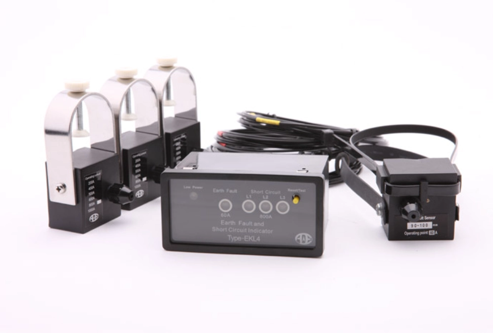
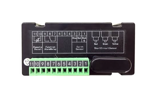
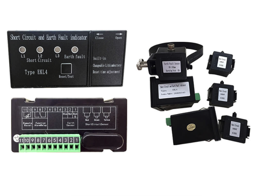
For example, Xinyuan Electric's EKL4 indicator supports separate adjustable grounding-current and short-circuit alarm thresholds. This arrangement allows the two detection functions to be configured for their intended purposes.
What Factors Affect an Earth Fault Indicator Alarm Threshold?
Grounding System and Expected Fault Current
The grounding arrangement strongly influences the current available during an earth fault. Solidly grounded systems may produce relatively high fault currents. Resistance-grounded systems limit current through the neutral grounding resistor. Isolated or compensated systems can produce different fault-current characteristics.
These differences affect the minimum current that a device may need to detect. A threshold suitable for one grounding arrangement may not work reliably in another. Engineers should review the network grounding design and calculate expected fault-current conditions. They should also consider the minimum fault current requiring detection, not only the maximum value.
Fault resistance can further reduce the current flowing through the fault path. High-resistance faults may therefore be difficult for current-based indicators to detect. The selected threshold must reflect the actual detection capability of the device. A setting alone cannot overcome limitations in the sensor or detection method.
Sensor Type and Detection Sensitivity
Sensor characteristics determine which signals an indicator can detect reliably. Relevant factors include the sensor's measurement range, accuracy, installation position, and compatibility with the device. Incorrect installation may distort the measured signal or prevent reliable fault detection.
The sensor arrangement must also match the cable configuration. For example, residual-current detection requires an appropriate measurement of the relevant current balance. Incorrect conductor routing through a sensor can affect the result. Engineers should follow the manufacturer's wiring diagrams and installation instructions.
Detection sensitivity describes the device's ability to respond to relatively small fault signals. Higher sensitivity may improve detection under certain conditions. However, sensitivity must remain compatible with normal network behavior and the device's intended application. Engineers should confirm the specified detection range instead of assuming that the lowest available setting is always best.
Response Time and Electrical Disturbances
Electrical disturbances can sometimes resemble fault conditions. Switching operations, transient currents, and changes in network conditions may influence the measured signal. If detection settings do not account for these conditions, unnecessary alarms may occur.
Where supported, response delays or additional detection conditions can help distinguish persistent faults from short-lived disturbances. However, excessive delay may slow fault identification. The appropriate response depends on the network's operating requirements and the indicator's capabilities.
Engineers should therefore evaluate the current threshold and response behavior together. They should also verify whether the device supports adjustable delays, automatic reset, or other detection logic. These functions vary by model and should never be assumed without checking the technical documentation.
How to Choose the Right Earth Fault Indicator Alarm Threshold
Selecting a suitable setting requires both network information and device specifications. The following steps provide a practical process for engineers, switchgear manufacturers, and commissioning teams.
1. Confirm the network grounding arrangement. Identify the neutral grounding method, rated voltage, cable configuration, and relevant operating conditions.
2. Determine the expected fault-current range. Use network calculations and the project's protection study to establish the fault currents requiring detection.
3. Check the indicator's technical limits. Review its available threshold range, sensor characteristics, measurement accuracy, and detection method.
4. Coordinate the settings with the protection scheme. Confirm that the indicator's behavior supports the intended monitoring and fault-location process.
5. Verify the selected setting. Use approved commissioning procedures to confirm detection performance and alarm output operation.
The selection should account for both the minimum fault current that needs detection and the normal signals present in the network. The device must detect relevant faults without responding unnecessarily to ordinary operating conditions. Engineers should document the final settings and obtain approval according to the project's procedures.
The following table summarizes the main selection factors.
| Selection factor | What engineers should verify |
|---|---|
| Grounding arrangement | Neutral grounding method and expected fault behavior |
| Fault-current range | Calculated minimum and maximum relevant fault currents |
| Sensor compatibility | Sensor type, rating, installation, and measurement range |
| Detection behavior | Threshold conditions and supported response-time settings |
| Protection coordination | Compatibility with the existing protection and monitoring scheme |
No single current value is appropriate for every installation. The correct setting must remain within the device's specified range and match the network's protection requirements.
How to Configure and Test an Earth Fault Indicator Alarm Threshold
Verify Device Settings Before Installation
Before installation, engineers should confirm the indicator's available settings and intended application. The manufacturer's technical documentation should specify the adjustment range and relevant sensor requirements. These details help prevent incorrect assumptions during equipment selection and commissioning.
Check the grounding-current threshold separately from the short-circuit threshold. Confirm the sensor connections, cable arrangement, and wiring diagram. If the device supports adjustable reset modes or alarm outputs, verify their configuration requirements. Record the approved settings for future inspection and maintenance.
For switchgear manufacturers and project contractors, reviewing these details before assembly can reduce commissioning problems. It also helps ensure that the selected indicator matches the electrical design. Any uncertainty about the available settings should be resolved with the manufacturer before energizing the equipment.
Validate the Alarm Threshold During Commissioning
Commissioning tests should verify whether the indicator responds according to its specified settings. Qualified personnel should use approved test equipment and manufacturer-recommended procedures. Tests should confirm the detection function and any supported local or remote alarm outputs.
Where the test procedure permits, engineers should verify the response near the configured threshold. They should also check whether the indicator resets as expected after the test condition ends. The results should be compared with the manufacturer's specified performance and the project's acceptance criteria.
Testing must not involve creating uncontrolled electrical faults on an energized network. Instead, personnel should follow the applicable safety procedures and use suitable test methods. After commissioning, the final settings and test results should be documented for later reference.
Troubleshoot Missed Faults and False Alarms
An indicator may produce unexpected results because of incorrect settings, unsuitable sensors, or installation problems. Raising or lowering the threshold immediately may not address the underlying cause. Engineers should first investigate the measurement system and operating conditions.
| Symptom | Possible cause | Recommended action |
|---|---|---|
| Repeated false alarms | Unsuitable settings or transient disturbances | Review detection conditions and recorded events |
| Missed earth faults | Excessive threshold or sensor problems | Check fault calculations, settings, and connections |
| Incorrect fault indication | Wiring or sensor placement problems | Verify the installation against the wiring diagram |
| Unexpected reset behavior | Incorrect configuration or operating conditions | Check reset settings and manufacturer instructions |
If the problem continues, review the event history and compare the measured conditions with the expected fault-current range. Confirm that the indicator is suitable for the network's grounding arrangement. Persistent problems may require additional testing or technical support from the equipment manufacturer.
How Does the EKL4 Earth Fault Indicator Support Threshold Selection?
EKL4 Short-Circuit Grounding Fault Indicator for Cables
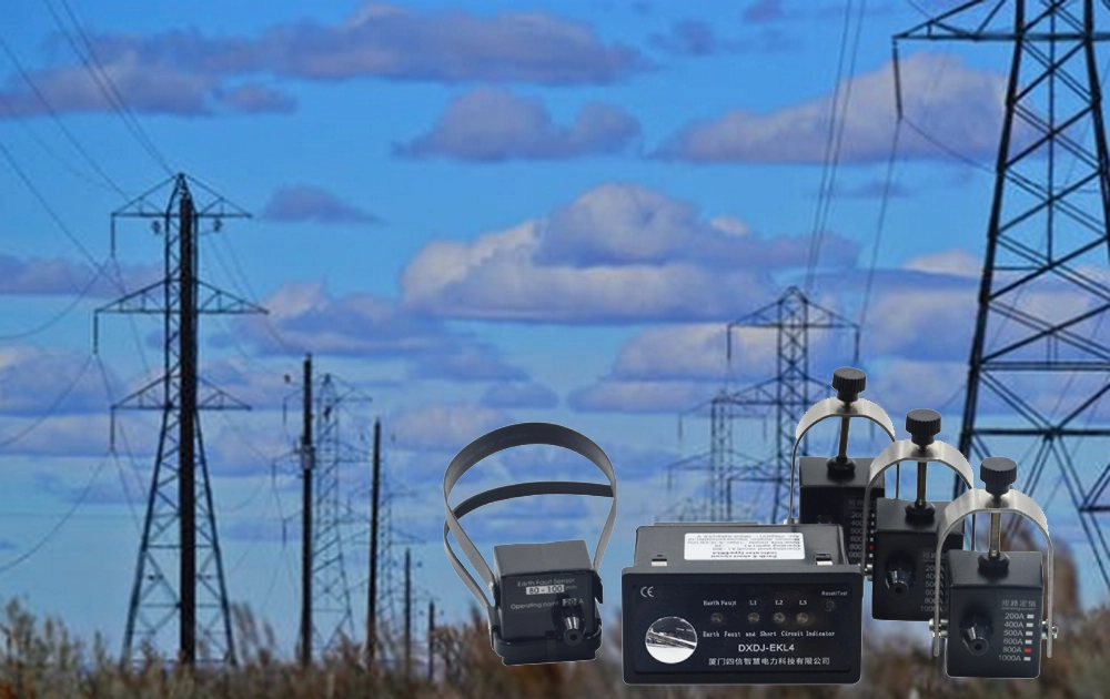
The EKL4 is designed for fault indication in ring main units, cable branch boxes, and medium-voltage distribution lines. It provides adjustable grounding-current and short-circuit alarm thresholds.
The EKL4 provides a practical example of how threshold settings support cable fault monitoring. Its published specifications list a grounding-current threshold range of 5–400 A. The typical factory short-circuit threshold is 630 A. These figures describe the specified product, not universal settings for all earth fault indicators.
When evaluating this device, engineers should compare the available settings with their network calculations and protection requirements. They should also confirm sensor compatibility and the intended installation conditions. The correct configuration depends on the actual project, rather than the product's maximum available threshold alone.
The EKL4 also supports automatic reset and alarm relay output. These functions can help integrate fault indication into maintenance and monitoring workflows. However, engineers should verify the required output behavior and reset configuration before specifying the device. They should not assume that an alarm relay automatically provides circuit-breaker tripping.
For switchgear manufacturers and distribution projects, reviewing these features during equipment selection can simplify system integration. The final configuration should be confirmed against the manufacturer's technical documentation and the project's commissioning requirements.
Frequently Asked Questions About Earth Fault Indicator Alarm Thresholds
What Is the Normal Alarm Threshold for an Earth Fault Indicator?
There is no universal alarm threshold suitable for every earth fault indicator. The appropriate setting depends on the network's grounding arrangement, expected fault current, sensor characteristics, and device specifications. Engineers should identify the minimum fault current requiring detection before selecting a value. They should then confirm that the selected setting falls within the manufacturer's specified adjustment range. Project protection studies and commissioning procedures should guide the final configuration. A value used successfully in one installation may not provide reliable detection in another. Therefore, engineers should avoid copying settings without checking the electrical conditions and intended application.
What Happens If the Earth Fault Alarm Threshold Is Too High or Too Low?
A threshold that is too high may prevent the indicator from detecting some relevant low-current faults. This risk is particularly important where grounding arrangements limit the available fault current. Conversely, an excessively low setting may increase unnecessary alarms when normal disturbances resemble fault signals. The actual outcome depends on the sensor, detection logic, and network conditions. Engineers should evaluate the expected fault-current range and normal operating signals before changing settings. They should also investigate wiring and sensor problems rather than using threshold adjustments to compensate for installation errors. Appropriate testing can help confirm whether the selected value provides reliable fault indication.
Does an Earth Fault Indicator Automatically Trip the Circuit When the Threshold Is Exceeded?
Not necessarily. Many earth fault indicators provide local visual indications or alarm outputs for maintenance personnel and monitoring systems. Their primary purpose is to help identify abnormal conditions and locate affected cable sections. Automatic tripping requires a suitable protection arrangement that can issue a circuit-breaker trip command. Some systems integrate monitoring devices with other protection equipment, but the functions depend on the overall design. Engineers should confirm the indicator's output capabilities and the connected protection logic before commissioning. An alarm indication alone should never be treated as proof that the affected circuit has been disconnected.