
Panel Mounted Fault Indicator: Functions And Installation
Panel mounted fault indicator functions, installation requirements, sensing methods, and selection factors for switchgear monitoring.
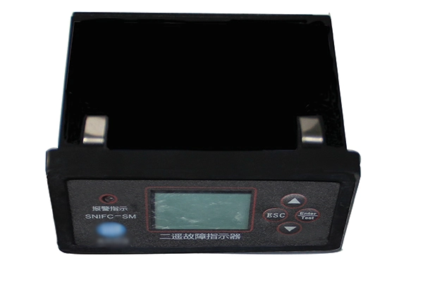
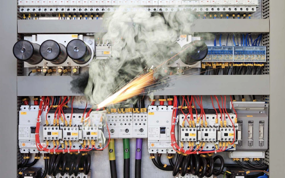
Electrical faults in distribution networks can interrupt power supply and complicate maintenance operations. Identifying the affected circuit quickly helps reduce inspection time and supports efficient service restoration. A panel mounted fault indicator provides visible fault information directly on the front of electrical switchgear. Unlike devices installed directly on conductors, panel-mounted designs allow operators to check fault conditions without accessing internal cable compartments. These indicators commonly support short-circuit detection, while some configurations also monitor earth faults. Their effectiveness depends on sensor arrangement, detection settings, and installation compatibility. Selecting an appropriate device requires consideration of mounting dimensions, display methods, electrical characteristics, and maintenance requirements.
What Is a Panel Mounted Fault Indicator?
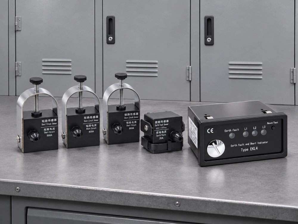
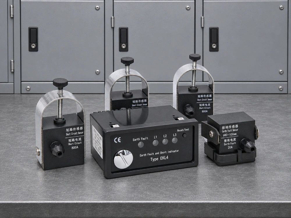
A panel mounted fault indicator is a monitoring device installed on the front panel of electrical distribution equipment. It provides visual information when a monitored circuit experiences an abnormal current condition. The system typically consists of a display unit, current sensor, and connecting components. Sensors detect fault-related electrical signals, while the front-mounted unit communicates the resulting status to operators. Depending on the product design, indication may use mechanical flags, LED lights, or other visual mechanisms. Some models include alarm contacts and reset functions. These devices commonly appear in medium-voltage switchgear, ring main units, and cable distribution cabinets. Their primary purpose is to assist fault location rather than interrupt electrical current. Protective relays and circuit breakers perform the actual fault-clearing operations.
How Does a Panel Mounted Fault Indicator Work?
A panel mounted fault indicator detects abnormal electrical conditions through current sensors installed around monitored conductors. During normal operation, current remains within the expected operating range. When a short circuit occurs, the current may increase significantly. The sensor detects this change and sends a signal to the indication unit. If the detection criteria are satisfied, the device activates its fault display. Earth-fault detection uses suitable residual-current or zero-sequence sensing arrangements. Some designs also evaluate fault duration to reduce unwanted indications during temporary current fluctuations. After activation, the indication may remain visible until a predefined reset condition occurs. Depending on the model, resetting can be automatic or manual. This operating sequence helps maintenance personnel identify potentially affected circuits during troubleshooting.
Main Components and Indication Methods
Panel-mounted fault indicators use different display mechanisms depending on their intended applications. Each design provides specific advantages regarding visibility, operation, and maintenance.
Mechanical Flag or Paddle Indicators: These devices use a mechanical display that changes position or appearance after fault detection. Their clear visual status makes them suitable for straightforward cabinet inspection. The Panel Mounted Paddle Type Short Circuit Fault Indicator is an example of this product category.
LED Fault Indicators: LED-based designs communicate fault conditions through illuminated signals. Their visibility can support inspection in electrical rooms with limited lighting.
Current Sensors: Sensors monitor electrical currents and provide signals for fault detection. Their arrangement depends on the monitored circuit and fault type.
Reset and Alarm Functions: Certain models support automatic resetting, manual operation, or auxiliary alarm contacts. Available functions depend on the individual product configuration.
Where Are Panel Mounted Fault Indicators Used?
A panel mounted fault indicator is commonly used in electrical equipment where operators need accessible fault information. In ring main units, it helps maintenance teams identify potentially affected feeder sections during network disturbances. Medium-voltage switchgear uses front-panel indication to support routine inspections and post-fault checks. Cable distribution cabinets benefit from visible fault signals because monitored conductors may be located inside enclosed compartments. Compact substations also use these devices when installation space and operating accessibility are important. Panel-mounted displays reduce the need to open equipment solely to inspect an indicator, although they cannot replace required electrical safety procedures. Their practical value increases when several monitored circuits are distributed across different cabinets. Operators can compare indications with network diagrams and protective-device records to narrow the fault investigation.
Installation and Wiring Requirements
Correct installation is essential for reliable fault indication and convenient maintenance. Before installing a panel mounted fault indicator, engineers should verify the cabinet's physical dimensions and electrical configuration. The mounting cutout must match the manufacturer's drawing, while sufficient clearance should remain behind the panel. Current sensors require appropriate positioning around the monitored conductors. Incorrect sensor placement can affect fault detection accuracy. Connecting cables should follow the specified wiring diagram and remain separated from components that could cause mechanical damage or electrical interference. Terminal connections must be secure and suitable for the operating environment. During installation, technicians should confirm display orientation, sensor compatibility, and reset accessibility. Functional testing should follow manufacturer instructions and approved electrical safety procedures before equipment enters normal service.
Panel Mounted vs. Cable Mounted Fault Indicators
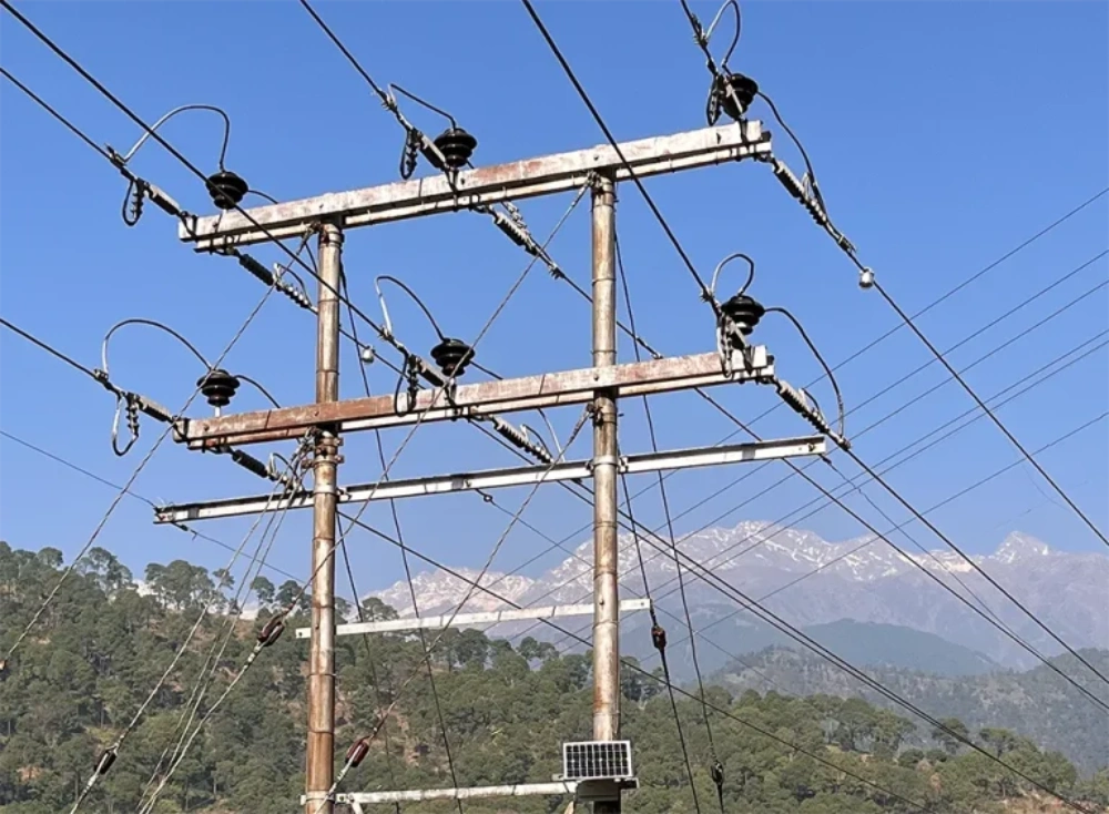
Panel-mounted and cable-mounted indicators share the purpose of identifying abnormal electrical conditions, but their installation arrangements differ. A panel-mounted system emphasizes accessible visual indication on the cabinet exterior. Cable-mounted designs place the monitoring device directly around or near the conductor, depending on their construction. Both approaches can be effective when properly matched to the application.
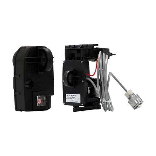
For example, the EKL4 Short-Circuit Grounding Fault Indicator for Cables supports short-circuit and grounding-fault monitoring in cable distribution applications. Its configurable detection thresholds and alarm functions illustrate important considerations when comparing fault-monitoring equipment.
| Comparison | Panel Mounted | Cable Mounted |
|---|---|---|
| Display location | Cabinet front panel | Cable area or connected display |
| Sensor arrangement | Often separate | Often integrated |
| Installation | Panel mounting and wiring | Cable mounting |
| Inspection | Accessible front display | Depends on installation |
| Main consideration | Panel compatibility | Cable compatibility |
Key Specifications for Product Selection
Selecting a panel mounted fault indicator requires evaluating both electrical performance and physical compatibility. Detection type is a primary consideration because some devices monitor short circuits, while others support combined fault detection. Pickup thresholds should correspond to expected operating currents and fault characteristics. Sensor compatibility is equally important, including conductor dimensions and the intended sensing arrangement. Engineers should also evaluate fault-current withstand capability, display visibility, and resetting requirements. Power supply arrangements vary between products and may influence maintenance planning. For cabinet integration, mounting dimensions and terminal configurations must match the available installation space. Environmental characteristics, including operating temperature and enclosure protection, should suit the installation location. Optional relay contacts may be useful when external alarm monitoring is required. Final specifications should always be confirmed against the selected model's technical documentation.
Maintenance and Fault Indication Checks
Regular inspection helps maintain reliable performance throughout the equipment's service life. Maintenance personnel should check whether the display remains visible and free from mechanical damage. Sensor connections, wiring terminals, and mounting components require inspection according to the manufacturer's recommendations. For battery-powered models, battery condition and replacement intervals should also be considered. Functional tests can verify whether the device responds correctly to simulated fault conditions and whether resetting operates as intended. Unexpected indications should be investigated rather than immediately treated as equipment failure. Incorrect threshold settings, sensor installation problems, and actual network disturbances may produce similar symptoms. A fault indication does not confirm that a circuit is safely isolated. Authorized personnel must follow appropriate isolation, voltage verification, and grounding procedures before performing electrical maintenance.
Frequently Asked Questions
Can a Panel Mounted Fault Indicator Detect Both Short Circuits and Earth Faults?
Some panel-mounted fault indicators can detect both short circuits and earth faults, but this capability is not universal. Short-circuit monitoring typically evaluates abnormal increases in conductor current. Earth-fault monitoring requires suitable sensing of residual or zero-sequence current. Combined models may use multiple sensors or specialized detection circuits to distinguish these conditions. Detection thresholds must suit the electrical network, particularly its grounding arrangement and expected fault currents. Before selecting a device, engineers should confirm its supported detection functions, sensor requirements, and adjustment ranges. A product designed exclusively for short-circuit indication should not be assumed to provide earth-fault monitoring without explicit manufacturer specifications.
Does a Panel Mounted Fault Indicator Need an External Power Supply?
Power requirements depend on the indicator's internal design and available functions. Some products use batteries to maintain fault monitoring and display operation. Other designs use auxiliary electrical supplies or obtain operating energy through current-sensing arrangements. Mechanical indicators may have different energy requirements from electronic displays and communication-enabled devices. Battery-powered units require attention to expected service life and replacement procedures. Externally powered models need a compatible voltage supply and appropriate wiring protection. Engineers should also verify how the indicator behaves when its power source becomes unavailable. This consideration is important because a blank display does not necessarily indicate a healthy electrical circuit.
Can a Fault Indicator Be Installed in an Existing Switchgear Panel?
Installing a fault indicator in existing switchgear is possible when the equipment provides sufficient physical space and compatible electrical connections. Engineers should first verify the required panel cutout, mounting depth, and display position. The cabinet must also accommodate the necessary current sensors and connecting cables. Existing wiring arrangements, insulation clearances, and maintenance access require careful assessment. Any modification must preserve the switchgear's applicable safety requirements and enclosure integrity. Sensor placement should follow the manufacturer's instructions to avoid inaccurate detection. After installation, technicians should perform connection checks and appropriate functional testing. Retrofit feasibility ultimately depends on the selected device and the original cabinet design.