
VDIS Indication Principle: How Voltage Detection Works
VDIS Indication Principle: How voltage detection works, signal coupling, indication thresholds, and electrical safety limits.
A Voltage Detecting and Indicating System (VDIS) helps operators identify the voltage status of medium-voltage switchgear. It provides a visible indication of whether operating voltage is present on the main circuit. This information supports routine inspections, switching operations, and maintenance planning.
The VDIS indication principle uses a coupling system to transfer a voltage-related signal from the primary circuit to an indicator. The indicator processes this signal according to its design and displays the corresponding voltage status. Reliable operation depends on electrical compatibility, correct installation, and proper functional verification. Knowledge of these operating principles also helps operators recognize the limitations of voltage indication during electrical work.
What Is the VDIS Indication Principle?
The VDIS indication principle describes how a voltage detecting and indicating system detects operating voltage and communicates the result to an operator. Rather than requiring direct contact with the energized conductor for routine panel indication, the system uses a coupling technology to obtain a signal from the primary circuit. An indicator then presents the detected state through a visual display.
VDIS is used in high-voltage equipment operating above 1 kV, including indoor and outdoor switchgear. Its primary purpose is to indicate the presence or absence of operating voltage under specified conditions. IEC 62271-213:2021 establishes requirements for VDIS design, performance, and interfaces. The system can also provide signals for other functions, such as phase comparison or voltage measurement, where the equipment supports them.
The exact configuration depends on whether the system is integrated into the switchgear or uses a separable indicator. In an integrated system, the coupling components, indicator, and testing interface form part of the equipment. In a separable arrangement, the indicator can be connected to a designated testing point. Both configurations follow the same general principle of obtaining and indicating a voltage-related signal, although their interfaces and operating procedures may differ.
How Does a VDIS Detect and Indicate Voltage?
The VDIS indication principle begins with a coupling system connected electrically to the primary circuit through a suitable sensing arrangement. Capacitive coupling is commonly used in medium-voltage switchgear. A capacitive sensor responds to the electric field associated with the energized conductor and produces a voltage-related signal. Some systems may use resistive coupling or other technologies, so the sensing method must be confirmed for the specific design.
The signal passes through the system's coupling and voltage-limiting components before reaching the indicator. The coupling arrangement establishes the relationship between the primary circuit voltage and the signal available to the indicating circuit. A voltage-limiting element helps control voltage at designated interfaces under specified fault conditions. Adjustment components may also be included to accommodate the electrical characteristics of the system. These elements must be designed to work together rather than treated as interchangeable parts.
A typical VDIS contains several functional components:
- Coupling system: Obtains a voltage-related signal from each phase of the primary circuit.
- Voltage-limiting element: Limits voltage at the testing or connecting interface under specified failure conditions.
- Indicator: Converts the available signal into a visible voltage-state indication.
- Testing point: Provides an interface for approved functional verification or other specified tests.
- Connecting lead: Transfers the signal between relevant components.
- Optional connecting point: Provides an interface for compatible external equipment or additional functions.
These components form a coordinated detection and indication chain. For an example of a panel-mounted display, the 92×44mm LCD High Voltage Indicator Display OEM/ODM can be considered when evaluating display format and switchgear integration. Its sensing components and electrical parameters must match the intended application.
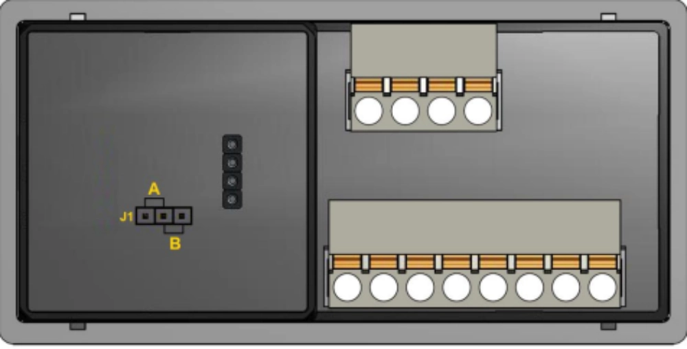
The signal path is not a universal circuit diagram. Component values, terminal arrangements, power supply requirements, and indicator electronics vary by product. Engineers should therefore refer to the manufacturer's wiring diagrams and technical specifications when integrating a VDIS into a switchgear assembly.
How Does a VDIS Indicate Different Voltage States?
A VDIS evaluates the signal received from the coupling system against the operating characteristics of the indicator. When the signal meets the applicable voltage-presence criteria, the indicator displays the corresponding state. When the signal falls below the specified threshold, the system may no longer indicate voltage presence. This does not necessarily mean that the primary circuit has reached zero volts.
The threshold is a key part of the VDIS indication principle. It defines the conditions under which the system changes its indication state. The threshold depends on the applicable standard, equipment design, and specified operating characteristics. Engineers must verify the rated voltage and frequency range, sensor parameters, and indicator compatibility instead of assuming that different VDIS models will behave identically.
In three-phase switchgear, the system typically provides separate indications for phases L1, L2, and L3. Each phase has its own coupling arrangement, allowing operators to observe the indicated state of each phase independently. If one phase shows a different state from the others, the discrepancy requires investigation. Possible causes include differences in the actual circuit condition, a sensor or connection problem, or an indication-system fault.
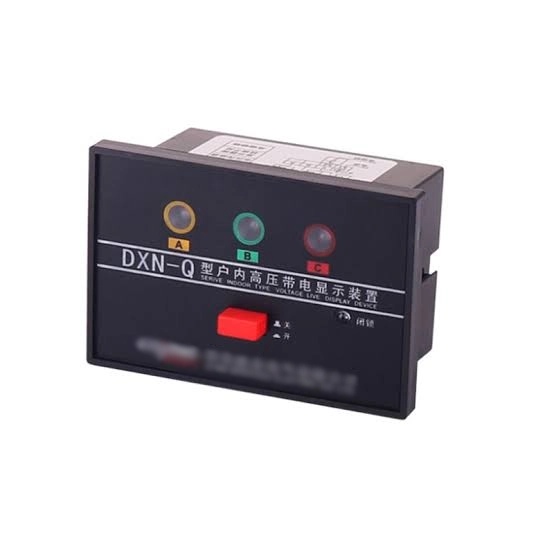
The visual output depends on the product design. Some indicators use LEDs, while others use LCD displays or different indication arrangements. For example, the DXN8D High Voltage Presence Indicator is designed for indoor medium-voltage switchgear applications. When evaluating this type of indicator, engineers should confirm its sensor compatibility, terminal configuration, and intended indication functions.
A three-phase display provides useful information about the monitored circuit, but it does not independently establish that the equipment is safe to access. Operators must interpret the indication according to the manufacturer's instructions and the site's electrical safety procedures.
What Affects VDIS Indication Accuracy and Reliability?
Reliable VDIS indication depends on the compatibility of the entire sensing and display arrangement. A suitable indicator cannot compensate for an incompatible coupling system, incorrect wiring, or inappropriate electrical parameters. Selection and commissioning should therefore consider the complete installation rather than the display component alone.
Important factors include:
- Rated voltage and frequency: The VDIS must be suitable for the electrical characteristics of the equipment on which it is installed.
- Coupling characteristics: Sensor capacitance, coupling technology, and related electrical parameters affect the signal delivered to the indicator.
- Wiring and connections: Incorrect terminal connections, damaged leads, or loose connections may interfere with signal transmission.
- Installation configuration: The sensor, indicator, and testing interface must follow the specified wiring and mounting arrangements.
- Environmental conditions: Temperature, moisture, contamination, and other site conditions may affect components or connections if they fall outside the specified operating range.
- Functional verification: The system should be checked using the manufacturer's approved procedures and suitable test equipment.
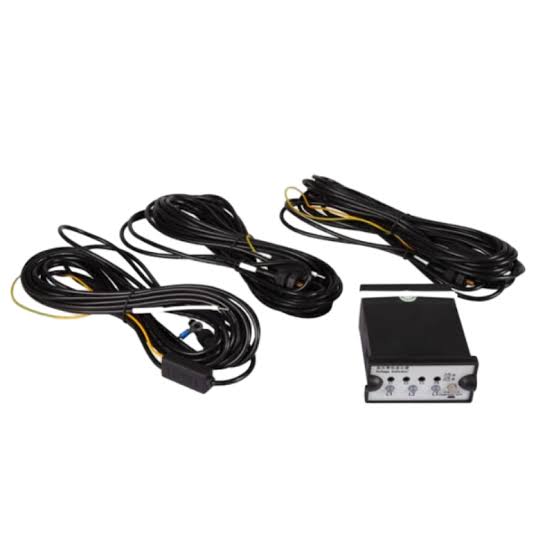
Commissioning should confirm that the indicator responds as intended and that each phase is correctly connected. Maintenance teams should investigate unexpected indications, missing phase signals, or inconsistent results before relying on the display for operational decisions. Any test must follow the applicable electrical safety procedures.
Some integrated VDIS designs also support continuous monitoring and provide interface signals for compatible external equipment. These functions can improve operational visibility, but their availability depends on the specific system. A basic voltage indicator should not be assumed to provide remote monitoring, self-diagnosis, or automatic interlocking unless these features are explicitly supported.
What Are the Limitations of VDIS Voltage Indication?
VDIS indicates voltage status within defined operating conditions. It is not necessarily a precision voltage-measuring instrument, and its display should not be interpreted as an exact measurement of the primary circuit voltage. The indication reflects the signal received through the coupling arrangement and the response of the system's detection circuitry.
A particularly important limitation concerns the difference between voltage not being indicated and a circuit being completely de-energized. IEC 62271-213:2021 specifies that VDIS is not intended to distinguish between voltage below 10% of nominal voltage and a dead-circuit state of exactly 0 V. Therefore, an indicator that does not show voltage presence cannot, by itself, establish that the circuit is at zero potential.
VDIS should also be distinguished from dedicated voltage detectors used in formal electrical safety procedures. Depending on the equipment and application, a separate voltage detector, an approved verification method, and additional safety measures may be required before work begins. Earthing and isolation procedures must follow the applicable regulations and site requirements.
A VDIS can provide a valuable operational reference, but it is only one part of an electrical safety system. Correct interpretation requires knowledge of the equipment, the system's limitations, and the procedures governing the work. Operators should never bypass required verification steps solely because the display shows no voltage.
Frequently Asked Questions About the VDIS Indication Principle
How does a VDIS work in medium-voltage switchgear?
A VDIS obtains a voltage-related signal through a coupling system connected to the primary circuit. Its indicating circuitry processes the signal and displays whether voltage presence has been detected under the specified operating conditions. Many medium-voltage systems use capacitive coupling, although other technologies are possible. The arrangement generally includes a coupling system, an indicator, a testing point, and associated connections. The exact components and signal path depend on the product design. Correct voltage rating, sensor compatibility, wiring, and functional verification are essential for reliable operation.
Does a VDIS use capacitive coupling?
Many VDIS installations use capacitive coupling because it can obtain a voltage-related signal from the electric field associated with an energized conductor. The coupling system is designed to provide a suitable signal to the indicating circuit without requiring the indicator to make direct contact with the primary conductor. However, capacitive coupling is not the only permitted technology. IEC 62271-213 also accommodates resistive coupling and other technologies. The actual method should be confirmed from the equipment documentation rather than inferred from the appearance of the front-panel display.
Does a VDIS indicate the exact voltage value?
Not necessarily. A conventional VDIS primarily indicates the presence or absence of operating voltage according to its specified threshold and operating characteristics. It should not automatically be treated as an instrument that measures and displays the exact primary circuit voltage. Some systems may provide additional interfaces or support other functions, but these capabilities depend on their design. If an application requires quantitative voltage measurement, the appropriate measurement equipment and compatible interfaces must be selected separately.
Does a VDIS showing no voltage mean the circuit is safe?
No. A no-voltage indication does not prove that the circuit is completely de-energized. Under IEC 62271-213, VDIS is not intended to distinguish between voltage below 10% of nominal voltage and a dead-circuit state at 0 V. Before electrical work, personnel must follow the required isolation, voltage verification, and earthing procedures. The applicable safety rules and equipment instructions determine which approved instruments and checks are necessary.
What should be checked if a VDIS gives an abnormal indication?
Start by following the site's safety procedures and preventing reliance on an unexplained indication. Qualified personnel should check the specified wiring, terminal connections, sensor compatibility, and rated electrical parameters. They should also consider whether the primary circuit's actual condition could explain the displayed state. Functional testing must use the manufacturer's approved method and suitable equipment. An abnormal or missing indication should not be dismissed as a display fault until the relevant system and circuit conditions have been assessed.