
VDIS Rated Voltage: Requirements And Selection
VDIS Rated Voltage requirements, insulation levels, and switchgear compatibility for selecting the right voltage indicator.
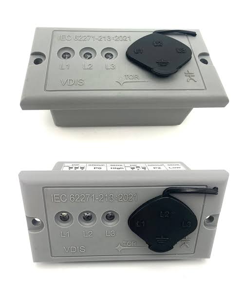
VDIS Rated Voltage is a key parameter when selecting a Voltage Detecting and Indicating System (VDIS) for medium-voltage switchgear. The system indicates voltage presence in the primary circuit, and its rated voltage must match the switchgear's rating. An incorrect match can affect compatibility between the indicator, coupling components, and switchgear.
IEC 62271-213 provides requirements for voltage detecting and indicating systems used with high-voltage switchgear and controlgear. These requirements cover rated voltage, insulation level, and indication performance. However, rated voltage alone does not establish whether a VDIS is suitable for every installation.
Selecting the correct VDIS requires checking the switchgear rating, system voltage, insulation requirements, frequency, and coupling arrangement. These factors help engineers verify that the selected system matches the intended application.
What Does VDIS Rated Voltage Mean?
VDIS rated voltage is the voltage rating assigned to a voltage detecting and indicating system for its intended application. Under IEC 62271-213, this rating must correspond to the rated voltage of the equipment on which the VDIS is installed.
A VDIS typically receives voltage signals through capacitive coupling components connected to the primary circuit. Its indicator processes these signals and displays the voltage presence status for the relevant phases. The displayed status helps operators assess whether voltage is present at the monitored connection points.
Rated voltage should not be confused with the instantaneous voltage measured by the system. It identifies the equipment voltage rating for which the VDIS is designed and specified. The actual indication depends on the complete sensing arrangement, the indicator, and their compatibility.
IEC 62271-213:2021 addresses VDIS applications in alternating-current systems with nominal voltages above 1 kV and frequencies from 16.7 Hz to 60 Hz. The applicable system and product specifications determine the exact requirements for each installation.
VDIS Rated Voltage vs. System Voltage and Insulation Level
Three electrical parameters are important when checking VDIS compatibility: rated voltage, system nominal voltage, and rated insulation level. Each parameter serves a different purpose, so one cannot replace the others during equipment selection.
| Parameter | Meaning | What to check |
|---|---|---|
| VDIS rated voltage (Ur) | The rated voltage assigned to the VDIS | It must match the rated voltage of the equipment on which it is mounted |
| System nominal voltage (Un) | The voltage used to designate the electrical system | Confirm the nominal voltage or declared voltage range supported by the VDIS |
| Rated insulation level | The specified withstand capability of the insulation system | Confirm that the VDIS insulation level is equal to or higher than the equipment requirement |
These distinctions follow the rating requirements of IEC 62271-213:2021.
The nominal voltage range is particularly relevant when a VDIS is intended for use across different system configurations. The manufacturer should specify the applicable lower and upper limits where a range is supported. Engineers should check those limits against the actual installation rather than assume that a single rated-voltage figure establishes compatibility.
Rated insulation level requires a separate check. It includes applicable insulation withstand parameters, such as lightning impulse withstand voltage and power-frequency withstand voltage. A VDIS with a matching rated voltage is not automatically suitable if its insulation requirements do not satisfy those of the switchgear.
How to Select the Correct VDIS Rated Voltage
Selecting the correct VDIS requires more than matching a voltage value printed on a product label. The indicator, coupling system, and switchgear must meet the requirements of the intended installation.
1. Confirm the switchgear rated voltage. Check the switchgear nameplate and technical documentation. Use the equipment's specified rating rather than relying only on the network's nominal voltage.
2. Verify the VDIS rated voltage. Compare the product's declared rated voltage with the switchgear rating. IEC 62271-213 requires these values to match.
3. Check the system nominal voltage. Confirm that the declared nominal voltage or nominal voltage range covers the intended electrical system. Do not assume that a VDIS supports multiple voltage levels unless its documentation explicitly states this.
4. Review the insulation level and frequency. Check the applicable insulation withstand values and confirm that the rated frequency matches the system. IEC 62271-213 identifies 16.7 Hz, 25 Hz, 50 Hz, and 60 Hz as preferred rated frequencies.
5. Confirm the coupling and connection requirements. Verify the capacitive or other coupling arrangement, sensor characteristics, wiring, and indicator compatibility. A voltage rating alone does not confirm that different components can operate together correctly.
6. Check operating conditions. Review the specified ambient temperature, humidity, altitude, and any special installation conditions. These factors may affect product suitability even when the electrical ratings match.
For procurement, it is useful to request the VDIS datasheet, rated voltage and insulation specifications, supported system voltage range, connection diagram, and applicable conformity documentation. Reviewing these details before ordering helps reduce compatibility problems during assembly and commissioning.
What Affects VDIS Voltage Indication Reliability?
Correct voltage ratings establish an important basis for compatibility, but indication reliability also depends on the complete sensing circuit and its installation.
The coupling system transfers a voltage-related signal from the primary circuit to the indicator. Its electrical characteristics must suit the intended switchgear and the indicator input. Incorrect coupling parameters or incompatible components can prevent the system from providing the expected indication.
Wiring and installation also matter. Loose connections, incorrect phase assignments, damaged connecting leads, or unsuitable component combinations can cause abnormal indications. Installation should follow the manufacturer's connection diagram, with each phase connected to its designated input.
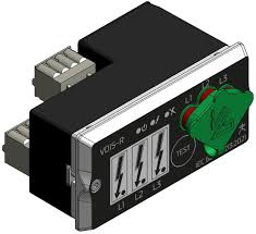
Some VDIS models also provide display test functions, diagnostic features, or relay outputs for remote indication and interlocking applications. Horstmann's WEGA product family illustrates these additional functions, including display testing and relay-based voltage status signaling.
These features support operation and monitoring, but they do not replace rated-voltage verification. Nor should a remote signal or successful display test be treated as proof that every part of the primary circuit is electrically safe.
Common Mistakes When Checking VDIS Rated Voltage
Several mistakes can lead to an unsuitable VDIS selection or incorrect interpretation of its display.
- Checking only the network voltage: The system's nominal voltage does not replace the requirement to match the VDIS rated voltage to the equipment rating.
- Ignoring insulation requirements: Matching rated voltage is insufficient if the VDIS insulation level does not meet the switchgear requirement.
- Assuming one product supports every voltage level: A product's usable nominal voltage or voltage range must be explicitly stated in its technical documentation.
- Overlooking coupling compatibility: The indicator and coupling components must be suitable for the same application and connected as specified by the manufacturer.
- Treating a display test as a complete system test: A display test checks a defined function. It does not necessarily verify every sensing component, connection, or primary-circuit condition.
- Equating a no-voltage indication with confirmed zero voltage: A VDIS has a defined indication threshold and is not intended to distinguish a voltage below 10% of nominal voltage from a truly dead circuit.
Environmental conditions must also remain within the product's specified operating limits. Temperature extremes, moisture, condensation, and contamination may affect components or connections. The applicable service conditions should therefore be checked before installation, especially for outdoor equipment or locations with unusual environmental demands.
The last point is particularly important for maintenance. A no-voltage indication alone does not prove that a circuit is completely de-energized. Personnel must follow the applicable safety procedures and use the prescribed voltage verification and earthing measures before beginning work.
Checking these issues during specification and commissioning helps prevent misunderstandings about both equipment compatibility and the meaning of the displayed voltage status.
VDIS Products for Medium-Voltage Switchgear
VDIS selection should begin with the electrical requirements of the switchgear and the intended sensing arrangement. Product dimensions, display format, mounting method, and sensor compatibility are also relevant when integrating an indicator into a medium-voltage cabinet.
The 92×44mm LCD High Voltage Indicator Display OEM/ODM is an option for switchgear projects requiring a front-panel LCD indicator. When evaluating this product, confirm the required voltage class, compatible voltage sensors, terminal arrangement, and panel cutout dimensions. These details help determine whether the display fits the intended cabinet design.
The DXN8D High Voltage Presence Indicator is designed for indoor medium-voltage switchgear applications. Its selection should take into account the switchgear configuration, sensor capacitance, wiring requirements, and any intended interlocking functions. The product's technical documentation should be checked to confirm electrical compatibility before ordering.
For either option, do not infer a specific rated voltage or IEC 62271-213 conformity from the product name alone. Request the applicable specifications and verify them against the switchgear requirements. This is particularly important for projects involving customized sensor parameters or OEM configurations.
Frequently Asked Questions
What Is the Rated Voltage of a VDIS?
The rated voltage of a VDIS is the voltage rating assigned to the system for its intended installation. Under IEC 62271-213, it must match the rated voltage of the equipment on which the VDIS is mounted. The system's nominal voltage or nominal voltage range must also be defined. When selecting a product, check its datasheet, supported voltage range, and insulation specifications rather than relying only on a general product description.
Must VDIS Rated Voltage Match Switchgear Rated Voltage?
Yes. IEC 62271-213:2021 specifies that the VDIS rated voltage must be the same as the rated voltage of the equipment on which it is installed. Its rated insulation level must also be equal to or higher than the equipment's rated insulation level. These are separate requirements, so both must be verified. Engineers should additionally check the system's nominal voltage range, rated frequency, and coupling arrangement to confirm that the complete system suits the application.
Can a VDIS Confirm That a Circuit Is Completely De-Energized?
No. A VDIS indicates the presence or absence of operating voltage within its defined detection thresholds. Under IEC 62271-213, it is not intended to distinguish a voltage below 10% of nominal voltage from a true zero-voltage condition. Therefore, a no-voltage indication alone cannot confirm that a circuit is completely de-energized. Before maintenance, personnel must follow the applicable safety procedures, use the prescribed voltage verification methods, and apply the required earthing measures.