High Display Voltage Presence Selection: Key Factors
Compare voltage presence displays by voltage rating, sensor compatibility, installation needs, safety features, and procurement needs.
Selecting a high voltage presence display requires more than checking its nominal voltage rating. Buyers must evaluate sensor compatibility, electrical characteristics, installation constraints, display functions, and operating conditions. An unsuitable device can create integration problems, unreliable indications, and additional replacement costs. These risks affect switchgear manufacturers, electrical engineers, system integrators, and procurement teams. A structured selection process helps identify potential mismatches before ordering. High Display Voltage Presence Selection should begin with the actual electrical system and its sensing arrangement. Buyers should also define the required functions, mounting dimensions, and acceptance criteria. Understanding these requirements makes supplier comparisons more meaningful. It also helps distinguish basic voltage indication from formal electrical safety verification.
How Does a High Voltage Presence Display Work?
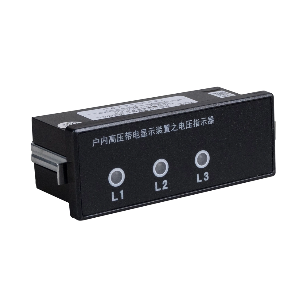
A high voltage presence display indicates detected voltage through a compatible sensing and indication arrangement. Capacitive systems commonly use sensors installed near conductors or integrated into switchgear insulation structures. These sensors couple electrical signals to an indicator through a designed electrical interface. The display then presents the detected condition, often through separate indicators for three phases. Different products may use different sensing circuits, signal thresholds, and indication logic. A Voltage Detecting Indicating System with Lock Function combines voltage indication with a specified locking-related feature. Buyers should verify the locking mechanism, operating conditions, and intended application before integrating it into switchgear. They should also confirm whether the device supports the required sensing arrangement. A voltage presence display provides operational information within its specified limits. It does not independently establish that equipment is safe to touch or completely de-energized.
How Should High Display Voltage Presence Selection Start?
The first step is to identify the electrical system and its actual operating requirements. Buyers should confirm nominal voltage, maximum equipment voltage, operating frequency, and the intended switchgear application. These values establish the initial selection boundaries, but they do not prove complete compatibility. Sensor specifications, connection arrangements, and manufacturer-defined operating limits also matter. A product labeled for a particular voltage class may not suit every installation within that class. Procurement teams should compare the full datasheet with the project requirements. They should also check whether the proposed indicator is approved for the intended sensor and switchgear configuration. High Display Voltage Presence Selection becomes more reliable when each requirement has a corresponding verification document. If specifications are unclear, buyers should request written clarification before approving a model. This approach reduces avoidable ordering errors and helps prevent unsuitable substitutions during production.
| Parameter | What to verify | Why it matters |
|---|---|---|
| Nominal system voltage | Actual network voltage | Establishes the basic application requirement |
| Maximum equipment voltage | Switchgear rating and applicable limits | Prevents selection based only on nominal voltage |
| Operating frequency | Supported system frequency | Helps confirm sensing compatibility |
| Sensor specifications | Approved sensor type and electrical parameters | Supports correct signal coupling |
| Connection arrangement | Terminal layout and wiring requirements | Reduces interface mismatches |
| Applicable standards | Project requirements and relevant product standards | Supports documented technical acceptance |
How Do You Match Sensors With Display Units?
Sensor compatibility depends on more than whether the connectors fit. Capacitive sensing arrangements may use a voltage divider, where the sensor capacitance and the indicator circuit influence the resulting signal. The relationship between these components depends on the circuit design and the manufacturer's specifications. Cable length and cable capacitance can also affect some sensing arrangements. Buyers should therefore confirm the approved sensor type, capacitance range, cable requirements, and connection configuration. They should not assume that a sensor and display will operate correctly simply because both support the same nominal voltage. An Inductive High Voltage Indicator Display may use a different sensing principle from a capacitive indicator. Its selection criteria must follow the relevant product documentation. For cross-brand combinations, request documented compatibility confirmation and any required engineering evaluation. High Display Voltage Presence Selection should identify the complete sensing chain, including sensors, connecting cables, and the display unit. This prevents assumptions about compatibility from replacing technical verification.
Which Display Type and Functions Do You Need?
LED and LCD displays serve different operational needs, and neither is universally better. LED indicators often suit applications requiring straightforward visual recognition of phase conditions. LCD displays may provide additional information, depending on their design and supported functions. Buyers should compare visibility, viewing distance, ambient lighting, operator workflow, and maintenance requirements. They should then assess optional functions against actual project needs. Three-phase indication helps operators distinguish individual phase conditions when the product supports separate phase displays. Test functions, phase-comparison features, and remote outputs may be available on selected models. However, these features are not interchangeable. A test function may check the indication circuit without proving the entire sensing path works correctly under every condition. Remote outputs also require compatible receiving interfaces. The final specification should identify each required function and its intended purpose. This avoids paying for unnecessary options while ensuring essential functions are not overlooked.
| Feature | Selection consideration | Question for the supplier |
|---|---|---|
| LED indication | Clear visual status recognition | Are phase states distinguishable under expected lighting? |
| LCD display | Additional information, depending on model | Which values or states can it display? |
| Three-phase indication | Individual phase visibility | Does the model indicate each phase separately? |
| Test function | Checking specified indicator functions | What does the test verify, and what remains unchecked? |
| Phase comparison | Comparing phase relationships where supported | What compatible equipment and procedure are required? |
| Remote output | Integration with monitoring or control systems | What output type and interface are provided? |
How Do Installation and Environmental Conditions Affect Selection?
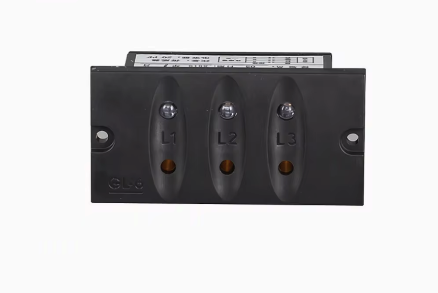
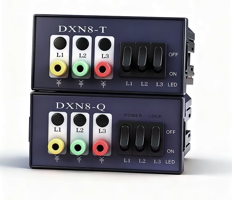
Mechanical compatibility should be confirmed before ordering a panel-mounted display. Buyers need the cutout dimensions, installation depth, terminal positions, and required wiring clearance. Existing switchgear may have limited space or fixed panel openings that restrict replacement options. Installation orientation and access for inspection should also be considered. Environmental conditions create another set of requirements. Temperature, humidity, condensation, contamination, and vibration can influence product suitability. The required enclosure protection should reflect the actual installation environment and the manufacturer's specifications. Buyers should not assume that all indicators support identical environmental conditions. For retrofit projects, compare the product drawing with the existing cabinet before approving the purchase. Check whether the terminals remain accessible after installation and whether the specified wiring can be routed correctly. Combining electrical, mechanical, and environmental checks reduces the risk of late design changes. It also helps ensure the selected product fits the intended switchgear arrangement.
What Causes Incorrect or Missing Voltage Indications?
An unexpected indication may result from an electrical condition, a sensing problem, or a fault in the indication circuit. A dark display could indicate an issue with connections, sensing components, or the indicator itself. Unequal phase indications may reflect a genuine system condition or a fault requiring investigation. The actual cause depends on the product's sensing principle and circuit design. Troubleshooting should therefore follow the manufacturer's documentation rather than assume every model behaves identically. Qualified personnel should inspect the relevant components under approved electrical safety procedures. They should also distinguish the function of a built-in test from verification of the complete sensing arrangement. A test feature may not identify every sensor, wiring, or system fault. Similarly, illuminated indicators should be interpreted according to the product's specified behavior. No indication must never be treated as proof of zero voltage. Formal absence-of-voltage verification requires the applicable safety procedure and approved test equipment.
How Can High Display Voltage Presence Selection Improve Procurement?
A clear procurement specification turns technical requirements into verifiable supplier commitments. Start by documenting system voltage, frequency, sensor model, connection arrangement, mounting dimensions, and required functions. Include environmental limits, applicable standards, labeling, and customization requirements where relevant. Ask the supplier to identify the exact model and confirm compatibility in writing. For customized products, approve the drawings and interface details before production begins. Sample evaluation should check the agreed electrical, mechanical, and functional requirements rather than appearance alone. Buyers should define acceptance criteria before testing, including which documents and inspection results are required. For bulk orders, confirm model identification, configuration consistency, workmanship, and traceability where applicable. Record approved drawing revisions and communicate changes through a controlled process. These measures help prevent differences between the approved sample and the delivered batch. They also make supplier comparisons more objective and reduce disputes over undocumented requirements.
| Procurement stage | Required action | Evidence to retain |
|---|---|---|
| Specification | Define electrical, mechanical, and functional requirements | Approved technical specification |
| Compatibility review | Confirm sensor, display, and interface matching | Supplier confirmation and relevant datasheets |
| Drawing approval | Check dimensions, terminals, and mounting details | Approved, revision-controlled drawings |
| Sample evaluation | Verify agreed product requirements | Inspection results and approval record |
| Production control | Confirm the approved configuration is maintained | Purchase specification and change records |
| Final acceptance | Check agreed quality and documentation requirements | Inspection records and applicable test reports |
For customized projects, buyers should also clarify responsibility for engineering changes and replacement compatibility. A revised sensor or display model can affect previously approved interfaces. The supplier should identify any changes that influence electrical characteristics, dimensions, or required testing. Procurement teams should establish which changes require renewed approval. They should also confirm the availability of installation instructions and relevant maintenance documentation. This process is especially useful when the same indicator will be purchased repeatedly or installed across several switchgear models. Clear records make future replacement and troubleshooting easier. They also reduce dependence on informal communications between engineering, purchasing, and production teams.
How Do You Verify Performance After Installation?
Installation verification should confirm that the delivered product matches the approved specification. Qualified personnel should inspect mounting, wiring, sensor connections, labeling, and relevant interfaces. Functional checks must follow the manufacturer's instructions and applicable project requirements. Where testing involves energized equipment, personnel must use approved procedures and appropriate protective measures. The verification should also confirm that optional outputs communicate correctly with their intended receiving systems. Any discrepancy should be documented and resolved before the equipment enters service. Maintenance records should identify the product model, inspection date, observed condition, and corrective actions. The required inspection frequency depends on the product instructions, operating environment, and applicable maintenance program. High Display Voltage Presence Selection should therefore extend beyond purchase and installation. Documented acceptance and appropriate maintenance help preserve configuration consistency. They also support reliable operation throughout the equipment's service life.
FAQ
Can a Voltage Presence Display Confirm Zero Voltage?
No. A voltage presence display indicates detected voltage under specified operating conditions. A dark display does not prove that equipment is completely de-energized. The indication could be affected by a sensing fault, wiring issue, or another abnormal condition. Electrical isolation must be established through the applicable safety procedure. Qualified personnel should use approved test equipment and follow the required absence-of-voltage verification process. They must also observe relevant lockout and tagging requirements. The exact procedure depends on the installation and applicable regulations. A presence indicator supports operational awareness, but it cannot replace formal electrical safety verification.
Can Different Brands of Sensors and Displays Work Together?
Possibly, but physical connection does not establish electrical compatibility. Different manufacturers may specify different sensor characteristics, interfaces, connection arrangements, and operating limits. Buyers should compare the relevant technical documentation before combining components. Written confirmation from the responsible manufacturer or engineering authority may be necessary. Cross-brand combinations may require a documented engineering evaluation. That evaluation should address the complete sensing and indication arrangement, not just the display unit. Unverified combinations can produce unreliable indications or fail to meet project requirements. For new switchgear projects, an approved sensor and display combination can simplify technical verification and procurement coordination.
What Information Should You Provide When Ordering a Voltage Display?
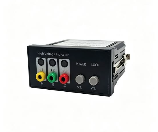
Provide the nominal system voltage, maximum equipment voltage, operating frequency, and intended application. Include the sensor model and relevant electrical specifications whenever available. Specify the required display type, phase indication arrangement, optional functions, and connection requirements. For panel-mounted products, provide cutout dimensions, installation depth, and available wiring space. Describe environmental conditions, applicable project standards, labeling requirements, and customization requests. Drawings or photographs of an existing installation can help clarify retrofit constraints. Finally, define sample approval requirements, inspection criteria, and requested documentation. Complete information helps suppliers assess compatibility and prepare an accurate quotation.