What Causes Earth Fault Indicator On RCD To Trigger?
An earth fault indicator on rcd triggers due to severe insulation breakdown, moisture ingress, or critical system wiring faults.
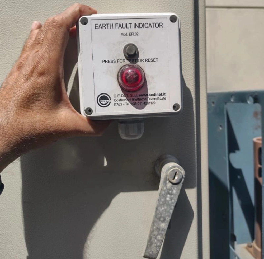
Defining the Role of an Earth Fault Indicator on RCD
Electrical systems in industrial facilities require continuous monitoring to ensure safety. An earth fault indicator on rcd serves as a vital component in these setups. It monitors residual current deviations to identify hazardous leakage paths. Engineers rely on this device to locate insulation breakdown rapidly. Such faults pose significant risks of electrical fire or severe shocks. Prompt identification prevents catastrophic damage to expensive production machinery. Modern factories operate complex distribution networks with high voltage demands. These environments require extremely precise safety instruments to maintain uptime. Unplanned power outages cause massive financial losses during peak manufacturing hours. Maintaining this equipment ensures compliance with strict international safety codes. Technicians must examine every signal to keep operations running smoothly.


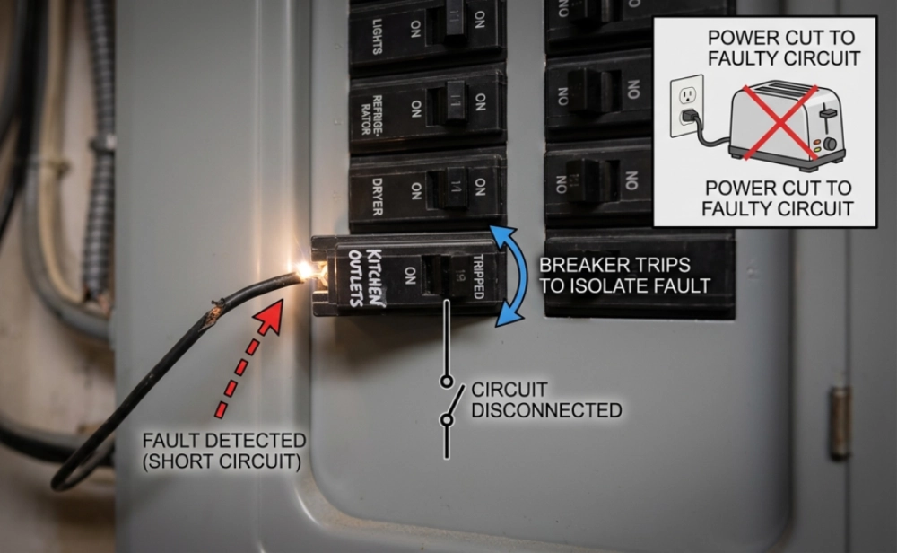
Core Operational Mechanisms of Residual Current Devices
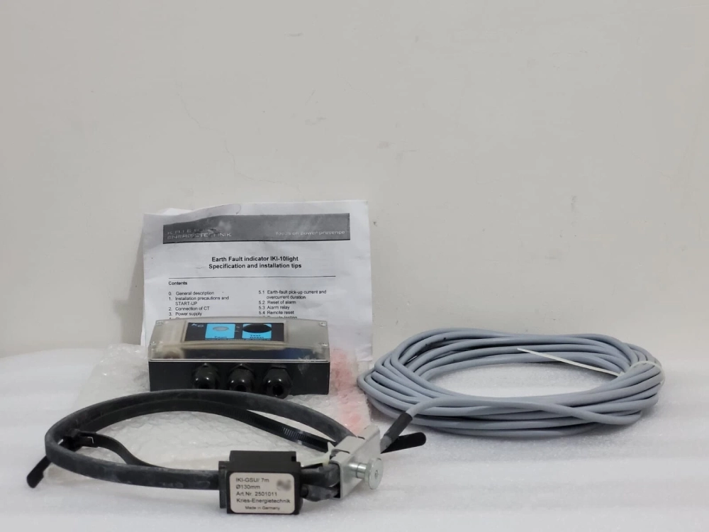
Residual current devices function by measuring current balance between conductors. They compare the outgoing current with the returning neutral current. Any discrepancy indicates that electricity is escaping to the ground. This leakage often travels through human contact or damaged insulation. Advanced industrial setups integrate the Integrated Indicator for Voltage Presence Grounding Fault. The specialized device assists in monitoring high-voltage busbar activities safely. Engineers track these parameters to prevent hazardous ground fault situations. System operators can identify phase imbalances before equipment experiences damage. Continuous monitoring ensures that small currents do not cause disasters. Such proactive measures protect sensitive electronic components from voltage spikes. Reliable current balance detection remains the cornerstone of modern engineering. Every industrial grid benefits from these precise safety monitoring configurations.
- Moisture ingress within outdoor terminal junction boxes
- Mechanical wear on rubber cable insulation sleeves
- Chemical exposure degrading protective wiring conduits
- Thermal overload from persistent motor overcurrent conditions
Primary Causes of Insulation Breakdown in Industrial Motors
Insulation degradation represents the primary trigger for ground faults. Moisture ingress inside junction boxes creates conductive bridges across terminals. This liquid path allows current to leak into the metal enclosure. Mechanical friction also wears down protective rubber sleeves over time. Exposed copper conductors then make direct contact with grounded parts. Chemical solvents in harsh environments dissolve polymer coatings on wires. Such erosion compromises the dielectric strength of the wiring material. Furthermore, thermal overload degrades internal motor windings during heavy operation. High temperatures melt the thin protective varnish coating the copper. These factors combine to create frequent paths for leakage current. Identifying these failure modes helps operators design better shielding. Proper enclosure selection prevents most environmental insulation failures completely.
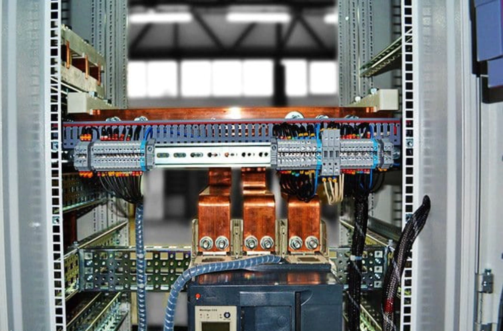
Environmental Stressors on Electrical Distribution Boards
Environmental conditions play a massive role in electrical system stability. Many industrial plants operate in dusty or wet surroundings. These severe conditions degrade the overall health of distribution panels. An active earth fault indicator on rcd warns of these issues. Technicians use these warning signals to schedule preventative panel cleaning. Overlooking these notifications can lead to major plant shutdown events. Accumulated conductive dust creates pathways for high current leakage. Chemical fumes corrode protective metallic casings of critical switches. This degradation lowers the overall resistance values of terminals. Addressing these environmental issues early improves plant safety scores. Regular thermal imaging audits help detect these hot spots. Proper cabinet ventilation remains crucial in hot manufacturing zones.
| Environmental Stressor | Primary Impact on System | Ground Leakage Risk Level |
|---|---|---|
| High Ambient Humidity | Condensation on terminal blocks | Medium to High |
| Corrosive Gas Exposure | Oxidation of copper connections | High |
| Conductive Dust Ingress | Tracking paths across insulators | Extremely High |
Deep Analysis of Leakage Sensor on Residual Current Device Actions
The compiled environmental data shows that conductive dust poses the highest danger. Carbon particles settle on circuit breakers and bridge live conductors. This bridging allows a low-resistance path straight to the chassis. Similarly, high humidity causes water droplets to collect on terminals. Liquid moisture acts as an excellent conductor for electrical current. Corrosive gases accelerate copper oxidation on vital electrical contact points. Oxidized copper increases resistance, which generates excess localized heat. Such thermal stress destroys surrounding wire insulation materials rapidly. Engineers must seal distribution enclosures using high IP-rated gaskets. Maintaining clean internal cabinet conditions prevents unexpected fault tripping. Every facility needs robust climate control for sensitive hardware. Implementing pressurized cabinets keeps harmful particulate matter outside safely.

Common Equipment Faults and Cable Degradation Scenarios
Older equipment often suffers from internal electrical insulation wear. Aging coils within solenoids degrade after years of continuous cycles. These internal failures create micro-leakage currents to the chassis. Engineers use advanced diagnostics to capture these minute signals. For example, installing the EKL4 W Current Temperature and Fault Online Monitor provides real-time oversight. This system tracks current anomalies and copper temperature rises simultaneously. Early warning alarms allow technicians to schedule maintenance before breakdown. Without monitoring, small faults quickly escalate into destructive phase-to-ground shorts. Replacing old cables with cross-linked polyethylene alternatives increases reliability. Modern materials resist thermal stress better than older rubber options. Protecting cables from physical vibration prevents mechanical sheath wear. Industrial facilities benefit immensely from implementing these active monitoring tools.
| Equipment Type | Common Failure Mode | Recommended Protection Standard |
|---|---|---|
| Three-Phase Induction Motor | Winding varnish thermal degradation | IEC 60034-18-1 |
| Submersible Pump | Shaft seal failure and water ingress | IEC 60364-7-702 |
| Power Transformer | Paper insulation chemical breakdown | IEEE C57.100 |
Engineering Evaluation of Ground Fault Monitor on Safety Switch Activities
Analyzing specific machinery failures helps clarify safety device behaviors. As the table shows, induction motors risk thermal breakdown. Varnish melting allows phase current to reach the stator frame. This direct contact immediately alerts an earth fault indicator on rcd. Similarly, pump seal failures allow water to contact live terminals. Water ingress triggers rapid tripping to prevent electrocution hazards. These situations require precise compliance with strict IEC standards. Following these safety standards ensures robust design in hazardous locations. Engineers must monitor winding insulation resistance using megohmmeters. Regular measurement identifies deterioration before ground leakage occurs. Replacing worn seals on wet machinery protects the overall grid. Proactive maintenance routines keep industrial systems safe and operational.
Resolving Persistent Earth Fault Indicator on RCD Alerts
Resolving constant trips requires a systematic physical inspection process. Technicians must isolate individual branch circuits to find the source. Disconnecting loads one by one reveals the leaking appliance. Next, testing insulation resistance with a megohmmeter pinpoint faults. This measurement identifies localized conductor failures inside conduit walls. Furthermore, checking connection terminals for tightness reduces micro-arcing risks. Clean the enclosures to remove accumulated dust and moisture traces. Replacing old breakers ensures that mechanical fatigue avoids causing false alarms. Modern panels utilize modular configurations to simplify troubleshooting tasks. Implementing these diagnostic steps maintains maximum uptime in plants. Staff training ensures rapid response to critical safety switch triggers. Reliable electrical distribution remains the backbone of safe production.

FAQ
How do engineers test a suspected faulty residual current device?
Engineers begin testing by pressing the integrated test button. This manual test verifies basic mechanical spring functionality. Next, they connect a calibrated electrical installation tester. Such instruments inject a precise simulated ground leakage current. The tester measures the exact tripping time in milliseconds. According to safety standards, tripping must happen very rapidly. Delayed tripping indicates a failing internal sensing coil. Technicians record these values to track breaker aging trends. Any unit failing the speed test must undergo immediate replacement. Regular diagnostic audits guarantee reliable protection for human workers. These routine procedures maintain safety across the industrial plant.