What Components Are Needed For Earth Fault Project?
Select quality hardware for earth fault indicator project to ensure reliable grid monitoring and fast distribution system recovery.


Modern electrical grids require constant supervision to prevent catastrophic failures. Engineers deploy specialized hardware to locate distribution system errors quickly. Utility managers frequently initiate an earth fault indicator project to protect valuable substations. These automation schemes isolate broken lines and maintain continuous power delivery. Purchasing managers must select durable hardware to withstand harsh outdoor conditions. High-quality detection devices reduce utility downtime and lower maintenance expenses. Choosing reliable components ensures long-term safety for high-voltage installations. Robust equipment prevents widespread blackouts during sudden grid surges. Technical specialists always evaluate component standards before starting installation work. The following review covers every vital device needed for a successful deployment. Proper planning guarantees optimal performance under heavy electrical loads.
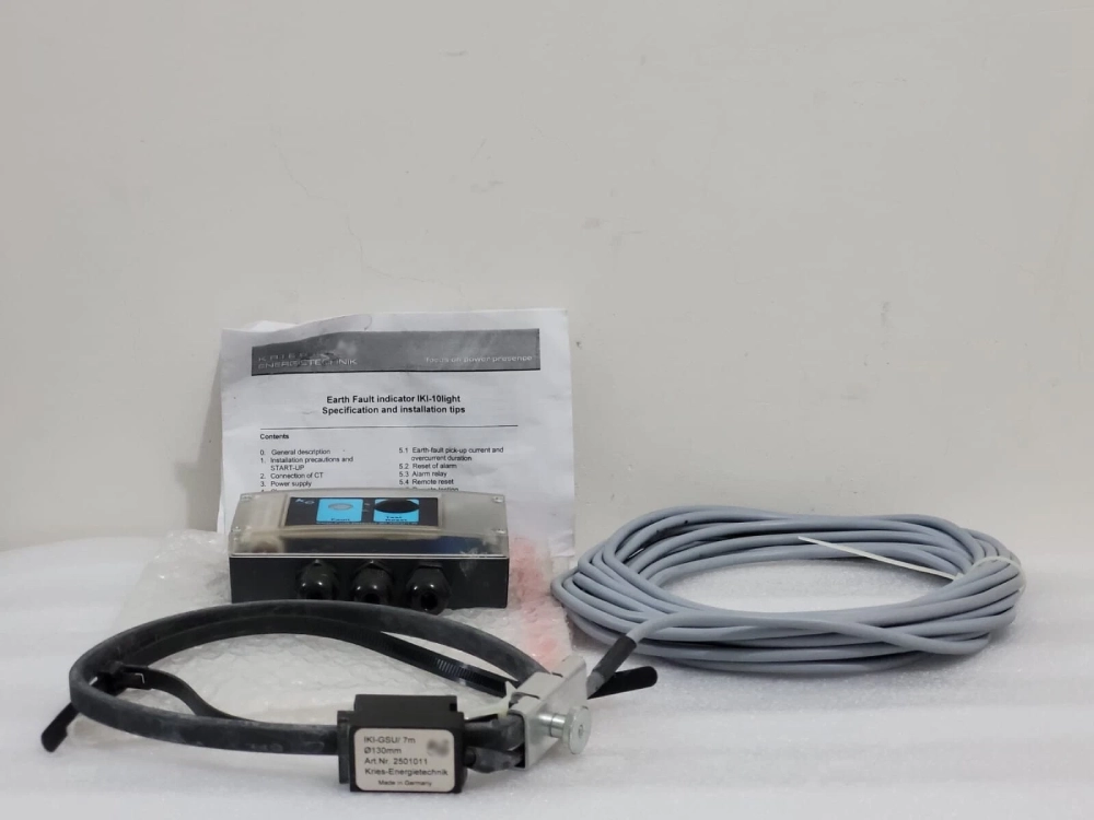
Core Sensors in an Earth Fault Indicator Project
Sensors form the primary layer of defense in medium-voltage distribution systems. They measure electromagnetic field variations to identify abnormal current spikes. Manufacturers construct current transformers using premium nanocrystalline magnetic cores. These specialized cores provide excellent permeability and prevent signal distortion. Cable installations often utilize the Integrated Indicator for Voltage Presence Grounding Fault to track voltage levels. This hardware accurately monitors insulation status and detects ground leakage instantly. Outdoor installations require split-core sensors to facilitate easy mounting without interrupting service. Heavy-duty epoxy resin seals the sensor body against moisture intrusion. Such insulation protects internal copper windings from thermal expansion damage. Grid operators receive precise analog signals during phase-to-earth short circuits. Reliable sensor data enables automatic isolation of damaged line segments.
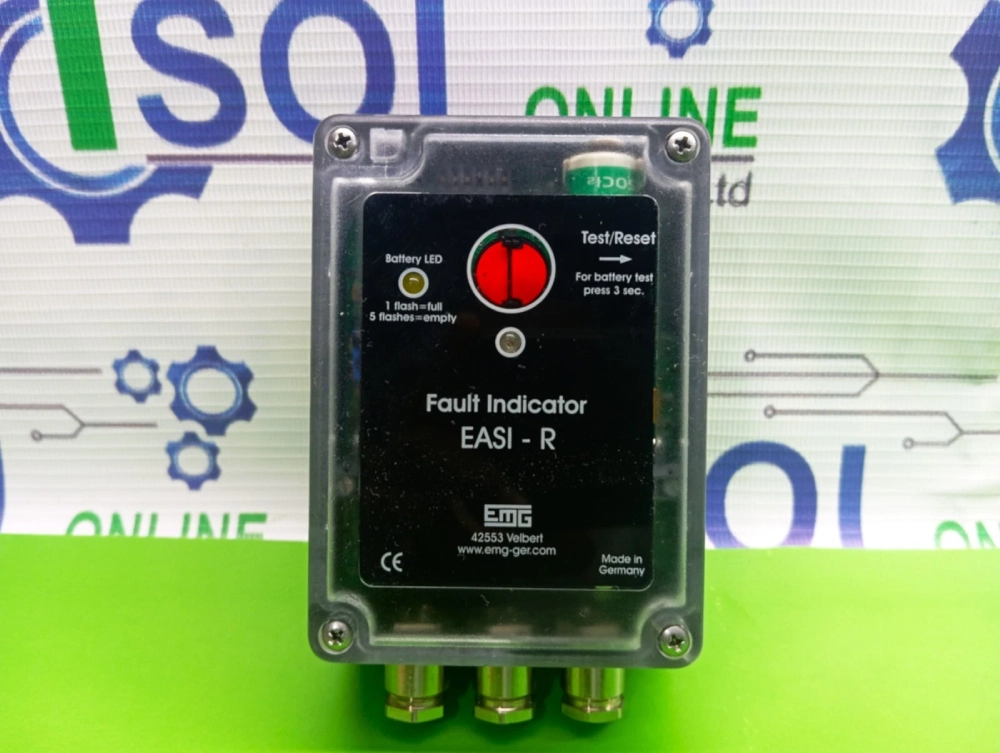
Central Receivers for Phase Fault Monitoring Setup
Receiver units process incoming physical data and display system status clearly. The EKL4 W Current Temperature and Fault Online Monitor serves as a central hub. It gathers telemetry from remote sensors and logs local temperature fluctuations. This device operates within substation cabinets to provide visible alarm signals. High-intensity LED indicators flash bright red when current exceeds pre-set limits. Operators configure trip current parameters manually or via remote command lines. Integrating this hardware secures your earth fault indicator project against sudden overcurrent. Built-in microprocessors filter out transient inrush currents to avoid false alarms. Reliable alarm logs remain in non-volatile memory even during power outages. External communication ports connect the monitor to substation automation networks. Modern utilities depend on these terminals to maintain distribution network safety.
Key Mechanical Fittings and Fiber Optic Connections
- Stainless steel mounting brackets for overhead line poles.
- Fiber optic cables for noise-free signal transmission.
- Weatherproof junction boxes with silicone rubber seals.
- High-voltage insulation tape for copper busbar protection.
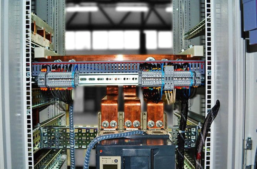
Mechanical Durability in Ground Leak Detection
Installing substation equipment requires robust mechanical parts to prevent physical failure. Stainless steel brackets withstand high wind loads and resist chemical corrosion. These metal fittings hold indicators firmly in place on overhead power lines. Fiber optic cables transfer signals from high-voltage lines to ground receivers. This optical transmission prevents electrical interference from disrupting delicate digital processors. Silicone seals protect junction boxes from heavy rain and desert dust storms. Utilizing premium physical accessories safeguards your earth fault indicator project from environmental wear. Technicians apply insulation tape to shield bare copper contacts from wildlife contact. Proper physical protection eliminates costly maintenance visits to remote mountain sites. Long-term physical stability reduces the total ownership cost of utility hardware. Smart design choices keep the distribution system running under severe weather.
Performance Metrics of Core Detection Equipment
| Component Type | Core Material | Detection Range | Ingress Protection |
|---|---|---|---|
| Current Sensor | Nanocrystalline Steel | 0A - 1000A | IP67 Rated |
| Voltage Indicator | Epoxy Coated Copper | 3.3kV - 40.5kV | IP65 Rated |
| Central Receiver | Industrial Polymer | N/A (Control Cabinet) | IP40 Rated |
Technical Analysis of Grid Voltage Detection Specifications
Selecting correct technical specifications prevents grid equipment failures during peak loads. The comparison table highlights the physical differences among vital measurement units. Current sensors utilize nanocrystalline steel to achieve high measurement sensitivity up to 1000A. Voltage indicators operate reliably on power systems ranging from 3.3kV to 40.5kV. These units utilize epoxy coatings to resist moisture in wet underground vaults. Outdoor elements demand IP67 ingress ratings to prevent dust and water damage. Central receivers sit inside steel cabinets and require less demanding IP40 protection. Choosing components with appropriate ratings guarantees continuous operation under stressful loads. Engineering teams use these metrics to draft purchase requisitions for substation upgrades. Buying certified hardware secures the utility grid against unexpected short circuit disasters. This selection process maintains network safety and ensures uninterrupted electricity delivery.
Communication Protocols for Short Circuit Sensor Deployment
| Protocol Type | Physical Medium | Maximum Range | Power Consumption |
|---|---|---|---|
| Modbus RTU | RS485 Wire | 1200 Meters | Low (Wired) |
| LoRaWAN | Sub-GHz Radio | 15 Kilometers | Ultra-Low (Battery) |
| DNP3 Cellular | 4G LTE / 5G | Global Network | Medium (Solar/Grid) |

Evaluating Communication Performance for Distribution Automation
Remote communication protocols determine how quickly dispatch centers receive critical system warnings. Wired Modbus setups offer reliable connections within single local electrical substations.These connections work well across short distances up to 1200 meters. Long-distance overhead lines require wireless transmission over cellular or radio networks.
LoRaWAN technology transmits fault signals across fifteen kilometers using ultra-low power. This long-range capability makes radio ideal for battery-operated remote sensor sites. Implementing cellular DNP3 transmitters provides unlimited communication range across regional grids. Such extensive coverage supports large utility providers managing a massive earth fault indicator project. Cellular hardware requires robust power sources like solar panels or line chargers. Engineering teams choose the protocol based on geography and local signal strength. This comprehensive analysis guarantees optimal signal delivery during severe grid emergencies.
Energy Supply Hardware for Pole Installations
- Lithium thionyl chloride cells for primary battery power.
- Solar harvesting panels for backup energy generation.
- Supercapacitors for high-current LED warning flashes.
Power Management and Battery Life Considerations
Outdoor grid sensors must operate continuously for years without scheduled battery replacements. Lithium thionyl chloride batteries provide stable voltage across extreme operating temperatures. These specialized cells withstand freezing winter conditions and scorching summer heat. Smart power-saving firmware keeps sensors in low-power standby mode during normal operations. The microprocessor activates transmission modules only when detecting actual fault current triggers. Solar harvesting systems provide secondary power to cellular transmitters on remote poles. This dual-source approach ensures communication links remain active during extended winter storms. Capacitive storage units supply quick bursts of power for high-intensity LED flashes. Utility buyers specify battery capacities based on expected annual warning frequency. Selecting reliable power components minimizes field maintenance costs over the system lifecycle. Secure power solutions guarantee constant readiness when short circuits damage electrical networks.
Optimizing Substation Security in your Earth Fault Indicator Project
Building reliable medium-voltage distribution grids requires selecting high-grade automation equipment carefully. Each component plays a vital role in preventing severe substation outages. Advanced current sensors track lines while reliable transmitters send alerts to control centers. Strong physical casings protect delicate microprocessors from rain, wind, and lightning strikes. Purchasing managers secure their long-term infrastructure by purchasing fully certified hardware. Utility teams select specific communication protocols that match regional cell tower coverage. This attention to detail prevents communication failures during massive storm events. Sourcing rugged parts guarantees stable performance for over a decade in the field. Proper planning ensures fast fault isolation and lowers operational repair costs. Invest in premium grid safety devices to secure continuous power delivery for customers. Safe networks foster business growth and increase energy provider reliability ratings.

FAQ
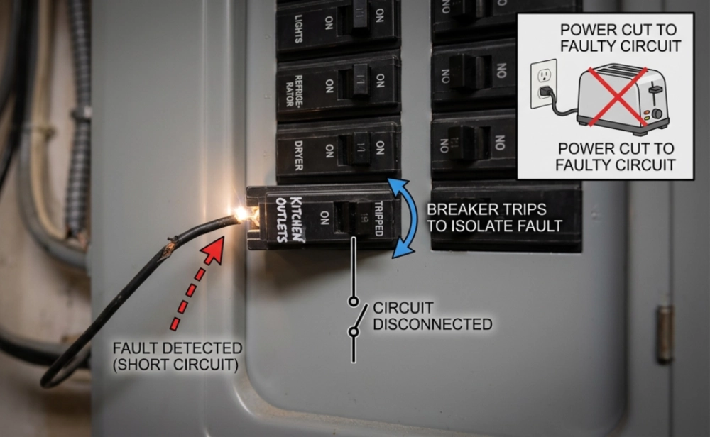
What is the main function of an earth fault indicator?
Earth fault indicators detect ground leaks in high-voltage power lines quickly. These units monitor phase currents and identify sudden imbalances. They flash local LED bulbs when an electrical short occurs. This immediate warning helps patrol teams locate damaged cables in the field. Installing these systems in an earth fault indicator project reduces grid downtime significantly. Modern models transmit real-time alert data directly to central SCADA systems. Automatic detection protects transformers from expensive thermal destruction. Utility companies achieve higher safety marks by deploying these reliable sensors. Rapid localization keeps emergency repair crews safe during maintenance operations. Fast response ensures constant energy transmission for local manufacturing clients.