What Does A High Voltage Presence Indicator Supplier Offer?
High voltage presence indicator supplier supports switchgear safety, voltage detection, OEM customization, testing, and system integration.
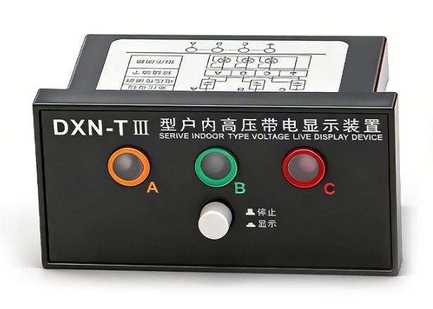
A high voltage presence indicator supplier provides more than a front-panel display. These systems help operators identify energized phases within high-voltage switchgear. Modern products can use capacitive or resistive coupling to connect with live circuit parts. IEC 62271-213:2021 covers voltage detecting and indicating systems for equipment above 1 kV. The standard addresses coupling systems, voltage indication, testing points, and related ratings. Suppliers therefore need strong electrical design capabilities and accurate production control. Buyers also need proper voltage matching before placing orders. A suitable product must match the switchgear's rated voltage and insulation level. Installation dimensions, connection methods, and environmental conditions also affect selection. These factors determine whether the indicator integrates correctly with the complete switchgear assembly.
What Functions Should High Voltage Presence Indicators Perform?
Voltage presence indicators primarily show whether operating voltage exists on monitored phases. They do not replace every electrical safety procedure or prove a circuit is completely dead. IEC 62271-213 defines VDIS equipment for detecting and indicating operating voltage presence or absence. The standard also distinguishes voltage indication from confirmation of a zero-voltage state. A typical three-phase system connects one coupling path to each phase. The indicator then provides visible status information through dedicated phase displays. Some systems also provide testing or connecting points for additional functions. Operators can use these points during commissioning and maintenance procedures. However, site procedures must define the required verification steps. A supplier should therefore explain the indicator's function without overstating its safety role. Clear technical documentation helps prevent incorrect operating assumptions.
What Components Form A Reliable Voltage Presence Indicator?
A reliable indicator combines electrical sensing, insulation, indication, and mechanical mounting components. The coupling system transfers a controlled signal from each energized phase. Capacitive coupling commonly uses an electrode or integrated capacitor within the high-voltage insulation structure. A voltage-limiting element then controls the signal reaching the low-voltage indication circuit. IEC 62271-213 identifies a coupling system and voltage-limiting element as system components. The indicator circuit converts this signal into a visible phase status. LEDs commonly provide separate indications for L1, L2, and L3. Mechanical housing protects the electronics from accidental contact and installation stress. Insulation materials also need stable dielectric properties across the specified temperature range. Suppliers should control component tolerances because capacitance directly affects the sensing signal. Poor dimensional consistency can create inconsistent indication behavior between production batches.
How Does A High Voltage Presence Indicator Supplier Support Switchgear?
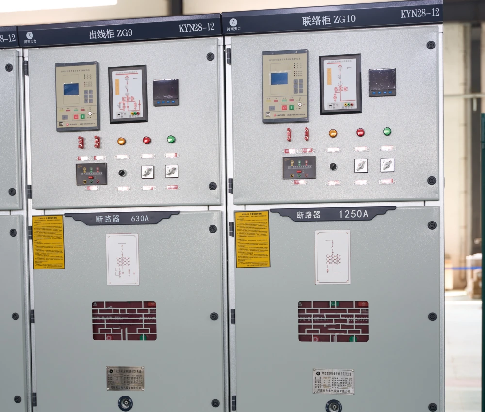
A capable high voltage presence indicator supplier should consider the complete switchgear architecture. The indicator normally connects with sensors associated with the main circuit. Its front display should remain visible without interfering with doors, operating handles, or cable compartments. Project specifications can also define indicator locations near incoming and outgoing cable connections. Some industrial specifications require three-phase voltage detection and indicating systems for specific switchgear applications. Incoming circuits, outgoing feeders, and bus coupler panels can all require appropriate indication. This requirement shows why product selection cannot rely on voltage rating alone. Engineers must review cabinet drawings, sensor locations, wiring paths, and panel cutouts. Suppliers can then confirm whether their indicator matches the intended assembly. Such coordination reduces installation changes during final cabinet production.
Which Voltage Ratings Should Buyers Check Before Ordering?
Voltage selection requires more than checking a nominal system value. IEC 62271-213 specifies that the VDIS rated voltage should match the equipment's rated voltage. Its rated insulation level should also match or exceed the equipment insulation level. Buyers should therefore review several parameters before approval.
| Parameter | What Buyers Should Check | Why It Matters |
|---|---|---|
| Rated Voltage | System voltage and equipment voltage class | Ensures suitable voltage detection performance |
| Power-Frequency Withstand Voltage | Specified insulation withstand level | Supports insulation coordination within the switchgear |
| Lightning Impulse Withstand Voltage | Required impulse insulation level | Helps match the indicator with equipment insulation requirements |
| Frequency | 50 Hz, 60 Hz, or project-specific frequency | Ensures correct sensing characteristics |
| Installation Environment | Indoor or outdoor conditions, altitude, temperature, and humidity | Supports reliable operation under actual service conditions |
| Coupling Parameters | Sensor type, capacitance, and connection configuration | Controls the signal delivered to the indication circuit |
| Mounting Dimensions | Panel cutout, terminals, depth, and fixing method | Prevents mechanical conflicts during cabinet assembly |
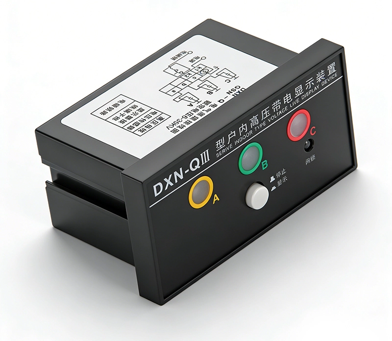
How Do Voltage Ratings Affect Indicator Selection?
These parameters should be evaluated as one technical package. For example, a 12 kV switchgear panel needs an indicator designed for the relevant equipment rating. A higher-rated device may still require mechanical and electrical compatibility checks. Frequency also matters because IEC 62271-213 specifies preferred frequencies including 50 Hz and 60 Hz. These details should appear clearly in the supplier's technical documentation. Buyers should also compare the indicator's insulation level with the complete switchgear specification. This prevents selection based only on the nominal voltage printed on the product label. Installation conditions deserve similar attention because temperature, humidity, and altitude can affect electrical performance. A complete specification review gives engineers a clearer basis for sample approval and bulk ordering.
How Are Presence Indicators Installed Inside Medium-Voltage Cabinets?
A high voltage presence indicator supplier should address installation design before production begins. The indicator may mount through the front panel while its sensing connections remain inside the high-voltage compartment. Engineers need to coordinate cutout dimensions, terminal positions, cable routing, and insulation clearances. The display should remain accessible without exposing users to energized components. Modern VDIS products can use integrated or separable arrangements depending on equipment design. IEC 62271-213 includes specific system structures and testing arrangements for these configurations. Field installation can also create additional wiring and verification work. Published manufacturer service information describes field installation on existing switchgear as complex because wiring and testing require proper verification. Factory integration can therefore simplify dimensional control and production testing. Buyers should provide cabinet drawings early when requesting OEM production.
What Standards Matter For High Voltage Presence Indicators?
Standards provide the technical framework for evaluating indicator performance. IEC 62271-213:2021 covers voltage detecting and indicating systems installed on indoor and outdoor high-voltage equipment. It replaced the earlier IEC 62271-206 framework for voltage presence indicating systems. IEC 62271-200:2021 covers AC metal-enclosed switchgear above 1 kV and up to 52 kV. Therefore, buyers should evaluate the indicator and the complete switchgear assembly together. Relevant documentation should state rated voltage, insulation level, frequency, environmental conditions, and applicable tests. Project specifications may impose additional requirements beyond the base standard. Suppliers should identify those requirements before production begins. A clear compliance matrix can connect each requested parameter with a test or document. This approach makes technical approval more transparent and reduces ambiguous procurement decisions.
How Does A High Voltage Presence Indicator Supplier Test Products?
Testing should cover both electrical performance and production consistency. A supplier can begin with incoming inspection for electronic components, insulation parts, terminals, and mechanical housings. Electrical testing should then verify indication behavior under defined voltage conditions. IEC 62271-213 includes type tests and routine tests for voltage detecting and indicating systems. Its testing framework includes visual indication, response time, current levels, and related electrical characteristics. Production testing also needs phase-by-phase verification. Each display channel should respond correctly when the corresponding sensing input receives the specified signal. Mechanical inspection should confirm panel dimensions and terminal positions. Batch records can connect test results with production lots. Buyers requesting OEM supply should also ask for sample test records. Consistent records provide stronger evidence than a general statement about factory quality.
What Customization Can Buyers Request From Suppliers?
OEM projects often require dimensional and electrical adjustments rather than completely new electrical principles. A supplier may modify the front-panel layout, mounting hole pattern, terminal arrangement, labels, or housing dimensions. Voltage class and sensor parameters can also require project-specific configuration. For example, KSG 12 High Voltage Indicator Display OEM/ODM can represent a customized product requirement for a defined switchgear application. The buyer should provide cabinet drawings before confirming the final design. Engineers can then check the available panel space and internal connection route. Customized labels can also match the customer's phase identification scheme. Packaging and documentation may follow the buyer's procurement requirements. These changes become easier when the supplier maintains standardized internal modules. A modular design can reduce development time while preserving tested electrical structures. OEM support should therefore combine customization with controlled engineering change procedures.
What Can A Real Switchgear Project Reveal About Supplier Performance?
A documented engineering case from the University of Maribor provides a useful practical example. Researchers developed and tested a voltage detecting system for medium-voltage switchgear. Their design used epoxy pin insulators, a capacitive voltage divider, and an electronic indicator unit. They also used electric-field calculations to optimize electrode geometry. Practical tests then confirmed the numerical design work on a prototype intended for medium-voltage switchgear. The case shows why sensor geometry cannot rely only on visual dimensions. Capacitance, electric-field distribution, insulation material, and indicator response all interact. It al
How Should Buyers Evaluate Supplier Technical Support?
A high voltage presence indicator supplier should provide technical support before the purchase order. Engineers should receive dimensional drawings, electrical specifications, wiring information, and applicable test documentation. The supplier should also confirm whether the proposed indicator matches the cabinet's rated insulation level. Sample approval provides an opportunity to verify installation and indication behavior. During this stage, buyers can check panel cutouts, terminals, phase identification, and sensor connections. Production teams should then freeze the approved configuration before mass manufacturing. Any later modification should pass formal engineering review. A supplier should also maintain records for critical component changes. This process helps preserve consistency across repeat orders. Technical communication becomes especially important when the buyer uses a proprietary cabinet design. Clear drawings reduce interpretation errors between electrical engineers and production technicians. Strong support therefore combines engineering response, documentation, samples, and controlled production changes.
How Does Supplier Selection Affect Long-Term Switchgear Reliability?
Supplier capability can influence reliability long after the initial installation. Voltage indicators operate as part of a larger electrical assembly rather than as isolated display devices. Their sensing components interact with primary insulation structures and cabinet geometry. Their displays also need to remain readable during routine switching and inspection activities. A suitable supplier should maintain consistent component specifications across repeated production batches. Replacement units should preserve the original electrical and mechanical parameters. Documentation should also remain available when maintenance teams need replacement parts years later. IEC 62271-213 provides a standardized framework for relevant VDIS characteristics and testing requirements. Buyers can therefore compare supplier documentation against the project specification. They can also request sample validation before approving large quantities.
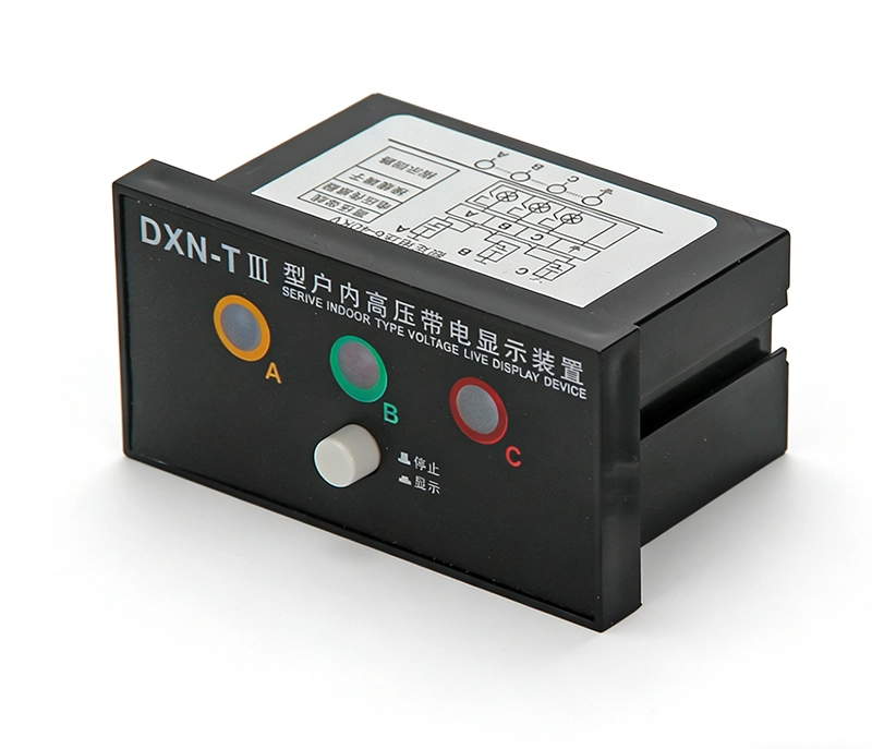
Long-term supply planning should cover spare units, technical records, packaging, and change notifications. These measures support stable switchgear operation throughout the equipment lifecycle.
What Should Buyers Ask Before Ordering A Voltage Presence Indicator?
Before placing an order, buyers should confirm the complete technical interface. The supplier should identify the applicable standard and product classification. Voltage rating, insulation level, frequency, sensing method, and installation environment should appear in the technical specification. The customer should also confirm whether the product supports integrated or separate sensing arrangements. DXN8D 12 Voltage Presence Indicating System is one example of a named product configuration used for medium-voltage voltage indication applications. Its specification should still be checked against the actual cabinet design. Buyers should request dimensional drawings before final approval. Sample testing can verify panel fit, phase indication, and connection accuracy. Factory test records can then support batch acceptance. Procurement teams should also confirm packaging and replacement arrangements. These checks create a traceable process from specification to delivery. They also reduce the risk of receiving a visually similar product with incompatible electrical parameters.
FAQ
What Is A High Voltage Presence Indicator Used For?
A high voltage presence indicator shows whether operating voltage exists on monitored phases. It commonly serves medium-voltage switchgear and other high-voltage equipment. Three-phase systems normally provide separate indication for each monitored phase. The sensing circuit receives a controlled signal through a coupling system. The display then provides a visible status indication to the operator. IEC 62271-213 covers these voltage detecting and indicating systems for equipment above 1 kV. However, the display does not replace every required electrical safety procedure. Operators should follow applicable operating instructions and site verification processes. Correct voltage matching also remains essential for safe and reliable operation.
How Does A Voltage Presence Indicator Work?
A voltage presence indicator normally uses a coupling system connected to each phase. Capacitive coupling is one established method for transferring a controlled electrical signal. The sensing structure reduces the primary voltage to a suitable signal for the indicator circuit. A voltage-limiting element controls the signal delivered to the electronic section. The display then indicates the operating voltage condition for each monitored phase. IEC 62271-213 allows capacitive, resistive, or other suitable coupling technologies. Actual construction depends on the equipment design and product architecture. Engineers must also consider capacitance, insulation, frequency, and environmental conditions. These parameters affect the sensing circuit and final indication performance.
What Should Buyers Ask A High Voltage Presence Indicator Supplier?
Buyers should request the rated voltage, insulation level, frequency range, sensing method, and applicable standard. They should also ask for dimensional drawings and connection diagrams. Sample testing should confirm panel fit and correct phase indication. Test documentation should identify the relevant electrical and functional checks. OEM buyers can additionally request customized labels, terminals, housings, or mounting dimensions. Production controls should cover critical components and configuration changes. The supplier should explain how it manages engineering revisions between samples and mass production. Buyers should also confirm replacement availability and technical documentation retention. These points provide a practical basis for supplier evaluation without relying on product appearance alone. A complete technical review can reduce compatibility issues during cabinet assembly and commissioning.