What Voltage Is Suitable For A Switchgear Light?
Switchgear light voltage depends on the auxiliary circuit, AC or DC supply, wiring, protection, and cabinet installation requirements.
The term switchgear light voltage describes the electrical supply required by an internal cabinet lamp. This value can differ from the primary circuit voltage. A switchgear assembly may contain separate power, control, protection, and auxiliary circuits. Internal lighting normally connects to an auxiliary circuit rather than the main power path. Therefore, engineers should identify the actual supply before selecting a fixture. Common supplies include 24 V DC, 48 V DC, 110 V AC, 120 V AC, 220 V AC, and 230 V AC. The suitable value depends on the cabinet's electrical design and project requirements. Lamp manufacturers also specify an operating voltage or voltage range. That specification must match the available supply type. Engineers should also check frequency for AC circuits and polarity for DC circuits. Correct matching prevents unstable operation, excessive heat, and premature component failure.
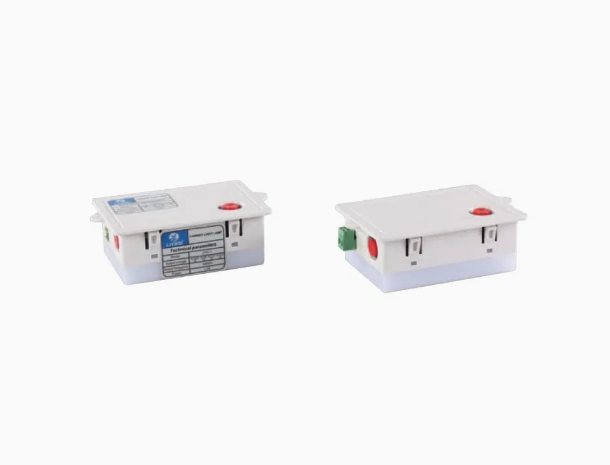
How Does The Auxiliary Circuit Determine switchgear light voltage?
The auxiliary circuit normally establishes the electrical conditions available for cabinet illumination. Engineers may obtain this supply from an auxiliary transformer, control transformer, DC system, or dedicated power supply. Industrial switchgear often separates these circuits from the primary power system. Consequently, a cabinet can handle high primary voltage while using a much lower auxiliary supply. The electrical schematic normally identifies the lighting branch and its supply terminals. Technicians can also inspect the protective device connected to that branch. These details provide stronger evidence than the cabinet's main nameplate voltage. A reliable selection process starts with the approved circuit diagram. Engineers should then verify the actual terminal voltage during commissioning. This approach helps identify variations caused by transformers, cable lengths, or shared auxiliary loads. The final lamp specification should reflect those verified operating conditions.
Which AC Voltages Are Common For Internal Cabinet Lighting?
AC lighting circuits can use different voltage levels according to the cabinet's auxiliary system. Industrial facilities often select voltage levels already available within their electrical infrastructure. Some installations provide 110 V or 120 V AC for auxiliary equipment. Other projects use 220 V or 230 V AC when local auxiliary distribution supports these values. Frequency also requires attention because many AC fixtures specify 50 Hz or 60 Hz operation. A lamp designed for one voltage should not automatically connect to another. Overvoltage can increase driver temperature and electrical stress. Undervoltage can reduce light output or prevent stable starting. Engineers should compare the lamp rating with the actual auxiliary supply before installation. The following table summarizes several common AC arrangements and their main selection considerations.
| AC Supply | Typical Application | Key Verification | Main Concern |
|---|---|---|---|
| 110 V AC | Industrial auxiliary circuits | Voltage and frequency | Transformer output compatibility |
| 120 V AC | Industrial and commercial systems | Voltage tolerance and frequency | Incorrect higher-voltage connection |
| 220 V AC | Selected auxiliary systems | Rated voltage and protection | Driver stress during variation |
| 230 V AC | Local AC auxiliary distribution | Voltage, frequency, and insulation | Fixture insulation requirements |
How Should AC Voltage Data Influence Lamp Selection?
The comparison shows why nominal voltage alone cannot determine a suitable fixture. Engineers must verify the auxiliary supply and its permitted operating range. A 230 V AC lamp requires a compatible 230 V AC circuit. Likewise, a 120 V AC fixture requires an appropriate 120 V supply. Frequency should match the manufacturer's specified operating conditions. Protection also matters because each lighting branch needs suitable overcurrent protection. Wiring length can introduce voltage drop when conductors run through large cabinets or long cable routes. Terminal connections should remain secure during repeated maintenance operations. Engineers should also consider temperature around the lamp and its electronic driver. A technically correct switchgear light voltage can still produce poor results when the fixture exceeds its environmental limits. Therefore, purchasing specifications should identify voltage, current type, frequency, protection, and installation conditions.
When Is Low Voltage Lighting A Practical Choice?
Low-voltage lighting can provide a practical option when the cabinet already contains a suitable low-voltage auxiliary circuit. A 24 V DC supply often appears in industrial control and instrumentation systems. Such an arrangement can simplify integration when the lighting branch shares the existing auxiliary source. However, lower voltage does not mean every lamp will operate correctly. The fixture must match the specified DC voltage and operating range. Cable resistance also deserves attention because lower voltage systems draw more current at equal power. Longer conductors can therefore produce a larger percentage voltage drop. Engineers should calculate expected current and conductor length before finalizing the design. Terminal resistance can become relevant when current increases. Protection devices should match the branch characteristics. These factors help determine whether low-voltage illumination fits the cabinet's existing electrical architecture.
How Does DC Supply Affect switchgear light voltage Selection?
DC auxiliary systems require additional checks because voltage and polarity both influence fixture compatibility. Many industrial installations use DC supplies for protection, signaling, control, and emergency functions. The lighting branch may therefore share a source with other auxiliary equipment. A fixture designed for 24 V DC must receive the correct DC supply within its specified range. Engineers should also verify positive and negative terminal identification when the driver requires polarity. A nominal DC value may fluctuate during charging, discharging, or changing auxiliary loads. Battery-based systems can create wider voltage conditions than regulated power supplies. The lamp should therefore tolerate the expected operating range. Designers should also confirm that the lighting load does not interfere with critical control functions. These checks become important in substations and industrial facilities where auxiliary DC systems support protection equipment.
What Happens When The Lighting Voltage Does Not Match?
Voltage mismatch can create different problems depending on whether the supply is too high or too low. Excessive voltage can increase current through sensitive electronic components and raise operating temperature. Continued thermal stress can shorten driver life and increase failure frequency. Insufficient voltage can reduce LED output and cause unstable starting. Some electronic drivers may repeatedly attempt to start when supply conditions remain outside their operating range. Such behavior can create intermittent illumination during inspection work. The problem can become difficult to diagnose when technicians assume the lamp itself has failed. Engineers should measure the supply at the actual lighting terminals rather than relying only on upstream specifications. Measurements should consider normal operating conditions and relevant auxiliary loads. Comparing those results with the fixture's rated range provides a practical compatibility check. This process can identify electrical problems before they become repeated maintenance issues. This check also confirms whether the selected switchgear light voltage suits the actual circuit.
What Installation Factors Affect Lighting Performance?
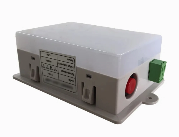
Electrical compatibility represents only one part of reliable cabinet lighting. Installation geometry also determines whether the lamp provides useful illumination across the working area. Engineers should position the fixture to illuminate terminals, wiring, indicators, and inspection points. Door movement can determine whether a door switch or manual switch suits the application. Wiring should follow a clear route and avoid unnecessary mechanical stress. The lamp should maintain sufficient clearance from heat-producing components. For example, the CM-L2 Cabinet LED Light for Switchgear can support internal visibility when its rated electrical supply matches the cabinet circuit. The installation team should verify mounting dimensions before drilling or modifying the enclosure. Terminal access should remain practical during future maintenance. Engineers should also consider the enclosure's temperature, dust conditions, and expected operating cycle. These factors influence long-term lighting reliability.
What Can A Real Switchgear Lighting Project Reveal?
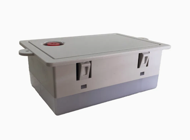
A practical example comes from a distribution cabinet used in an industrial production facility. Maintenance technicians reported poor visibility during evening inspection work. The existing lamp used manual switching, but the switch sat behind nearby control wiring. Access became inconvenient whenever technicians needed to inspect terminals quickly. The lighting conductors also followed an untidy route beside several control cables. The cabinet manufacturer reviewed the auxiliary circuit before changing the lighting arrangement. The team confirmed the available supply at the auxiliary terminals. They then moved the lighting protection point to an accessible auxiliary distribution location. A door switch controlled the lamp when technicians opened the cabinet. The revised wiring route also improved separation from nearby control conductors. A CM-1 Cabinet Light for Switchgear can serve similar applications when its rated supply matches the circuit. This case shows why electrical and installation factors should be evaluated together.
How Should Manufacturers Verify The Selected Lighting Circuit?
Manufacturers should verify the complete lighting branch before approving a cabinet for production. Engineers should first compare the approved schematic with the physical wiring arrangement. Next, they should confirm the auxiliary supply at the lighting connection point. The lamp rating should then be checked against measured operating conditions. Functional testing should cover normal switching, repeated operation, and continuous illumination. Teams should inspect terminals after extended operation for abnormal heating or loose connections. LED fixtures also require attention to driver behavior under supply variation. IEC 61439 provides requirements for low-voltage assemblies, including technical characteristics and verification processes. Manufacturers should integrate auxiliary circuit checks into their broader cabinet verification procedures. Documentation should record the selected lamp voltage, circuit source, protection, and switching method. This information gives maintenance teams a reliable reference for future component replacement.
What Should Buyers Check Before Ordering A Cabinet Light?
Purchasing teams can use a structured checklist before confirming a cabinet lighting order. The following items cover the main electrical and mechanical considerations.
- Confirm the nominal supply voltage and allowable tolerance.
- Confirm whether the circuit uses AC or DC power.
- Check AC frequency when an AC fixture is required.
- Verify polarity requirements for DC fixtures.
- Confirm rated power and expected current.
- Check mounting dimensions and terminal configuration.
- Review the expected enclosure temperature range.
- Confirm the switching method and control arrangement.
- Check project-specific certification requirements.
- Record the selected electrical specification on the purchase order.
How Should Buyers Apply These Technical Checks?
These checks connect the lamp specification with the cabinet's actual electrical architecture. Engineers should first verify the auxiliary source shown on the approved electrical drawing. They should then compare that source with the fixture's rated input range. Voltage tolerance deserves attention because nominal values can differ from measured operating values. AC systems also require frequency verification, while DC systems require polarity checks. Cable length should receive attention when the lighting branch uses lower voltage. Long conductors can create measurable voltage loss under operating load. Protection devices should also match the lighting branch and conductor capacity. Mechanical factors remain important because the fixture must fit the available mounting space. Clear procurement documents can prevent incorrect substitutions during production. This process also gives maintenance personnel a reliable specification for future replacement.
How Can Voltage Options Be Compared During Procurement?
A second comparison can help purchasing teams evaluate common supply arrangements. The table focuses on electrical characteristics that influence fixture selection and cabinet integration.
| Supply Arrangement | Voltage Example | Important Check | Selection Focus |
|---|---|---|---|
| Low-voltage DC | 24 V DC | Polarity and voltage range | Existing control supply compatibility |
| Higher DC auxiliary | 48 V DC | Polarity and operating range | Dedicated auxiliary systems |
| Industrial AC auxiliary | 110–120 V AC | Voltage and frequency | Transformer and branch compatibility |
| AC distribution supply | 220–230 V AC | Voltage, frequency, and insulation | Local auxiliary distribution compatibility |
Why Should The Complete Cabinet System Determine The Final Choice?
The complete cabinet system should determine the lighting specification rather than the primary circuit alone. A switchgear assembly can contain several electrical levels within one enclosure. The main power circuit may operate at a much higher voltage than the auxiliary lighting branch. Control circuits can also use separate AC or DC supplies. Engineers should identify the actual lighting source from approved electrical documentation. They should then verify voltage, current type, frequency, protection, and wiring conditions. The fixture's rated operating range should cover the expected supply conditions. Mechanical clearance and thermal conditions should also meet the fixture's requirements. A suitable switchgear light voltage should remain reliable during routine inspection and maintenance. Procurement teams can reduce errors by recording complete electrical requirements before ordering. This method also makes future replacement easier because technicians can identify the required specification without guessing from the main cabinet rating.