Why Choose A Cam Lock Disconnect Switch?
Cam lock disconnect switch ratings, pole options, safety features, installation needs, and durability for reliable equipment selection.
A cam lock disconnect switch provides direct manual control for electrical equipment. Its rotary mechanism changes contact states through a defined mechanical sequence. Operators can select, isolate, or transfer circuits without complex electronic controls. This design suits machines that need dependable local switching. Proper selection also helps maintenance teams create clear isolation points. Electrical ratings must match voltage, current, load type, and switching duty. Pole count also determines which conductors the device controls. Enclosure selection matters when equipment operates outdoors or in dusty areas. Many industrial installations use rotary switches for motor control and power transfer. Their mechanical construction can simplify troubleshooting during routine maintenance. These characteristics make rotary switching suitable where simple and predictable circuit control remains important.
How Does A Cam Lock Disconnect Switch Support Manual Isolation?
A cam lock disconnect switch uses a rotating shaft to control several electrical contacts. Each cam profile determines when individual contacts open or close. Turning the handle moves the shaft through defined positions. Internal springs maintain contact pressure during normal operation. Multiple contact blocks can operate together from one rotary movement. This arrangement supports isolation, changeover, reversing, and circuit selection. IEC 60947-3 covers switch-disconnectors and related low-voltage switching equipment. Engineers should verify whether the selected product meets the required utilization category. Motor loads can impose greater electrical stress than resistive loads. Therefore, current capacity alone cannot determine suitability. The switching duty must match the actual equipment and operating cycle. Proper contact spacing also supports reliable interruption during normal operating conditions.
What Makes The Compact Rotary Design Valuable?
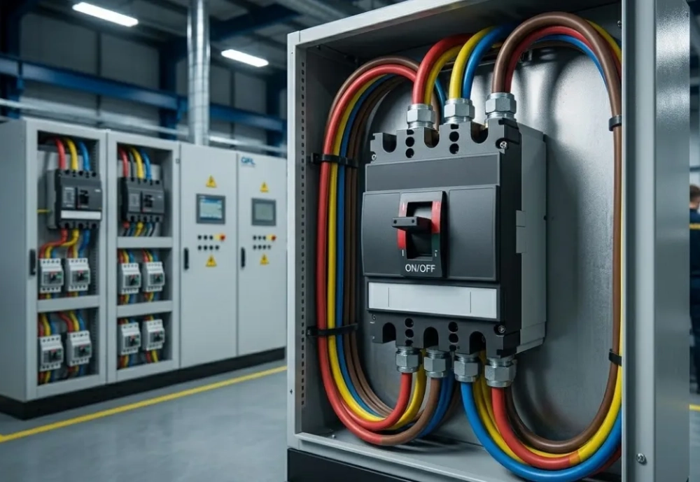
Compact construction can save valuable space inside electrical cabinets. Traditional contactor arrangements may require several components and additional control wiring. A rotary mechanism can combine multiple switching functions within one assembly. Panel builders can therefore reduce component count in suitable applications. Front mounting also gives operators direct access to the handle. Some designs support screw mounting, DIN rail mounting, or enclosure mounting. Terminal access can influence installation time and future maintenance effort. Finger-safe terminal designs provide another useful consideration for panel builders. Enclosure depth should accommodate wiring bend radius and terminal clearance. Engineers should check the complete dimensional drawing before approving a replacement. Mechanical compatibility matters as much as electrical compatibility. A smaller device should never replace a larger unit without rating verification.
Which Electrical Ratings Should Buyers Check?
Electrical ratings provide the foundation for selecting a suitable switching device. Voltage rating defines the highest system voltage under specified operating conditions. Current rating indicates continuous current capability under defined thermal conditions. Load category determines how the contacts handle switching stress. Motor circuits usually create greater contact stress during starting and stopping. AC-23 applications involve switching motor loads under defined conditions. Resistive loads can require different switching characteristics than induction motors. DC applications require separate evaluation because electrical arcs behave differently. Buyers should check pole count and switching positions. Short-circuit protection remains necessary because a disconnect does not replace upstream protection. Thermal limits also depend on ambient temperature and enclosure conditions. These factors should appear clearly in the technical specification before ordering.
| Selection Parameter | What It Controls | Why It Matters |
|---|---|---|
| Rated voltage | Maximum operating system voltage | Controls insulation and contact stress |
| Rated current | Continuous load current | Controls thermal performance |
| Utilization category | Switching duty and load behavior | Matches equipment with actual load conditions |
| Pole count | Number of switched conductors | Supports correct phase isolation |
| Switching positions | Available circuit states | Determines control and transfer functions |
How Do Poles And Switching Positions Affect Control?
Pole configuration determines how many electrical paths change during each handle movement. Three-phase motor circuits often require three switched phases. Four-pole versions can also switch the neutral conductor when system design requires it. Multi-position devices provide several controlled states from one rotary actuator. A forward-off-reverse arrangement illustrates this principle clearly. The central off position separates the active circuit before another direction engages. This sequence helps prevent unsafe phase transitions in suitable motor applications. Some rotary switches also provide auxiliary contacts for indication or control signals. These contacts can communicate the selected position to a PLC or indicator lamp. Engineers should confirm contact timing when auxiliary signals control other equipment. The cam profile determines this timing inside the mechanism. Custom switching sequences may require dedicated contact arrangements and verified terminal diagrams.
- Confirm the number of switched phases.
- Define every required handle position.
- Specify maintained or momentary operation.
- Check auxiliary contact requirements.
- Confirm terminal numbering before wiring.
- Verify the required isolation position.
Where Does A Cam Lock Disconnect Switch Fit Best?
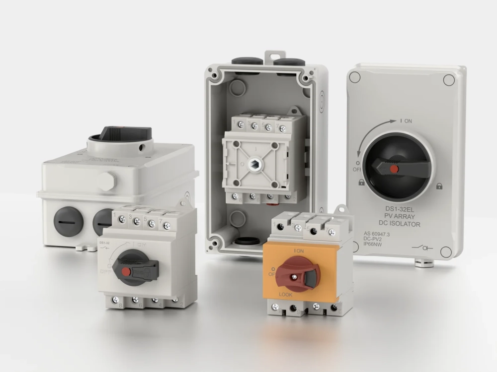
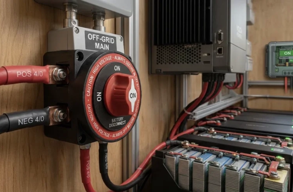
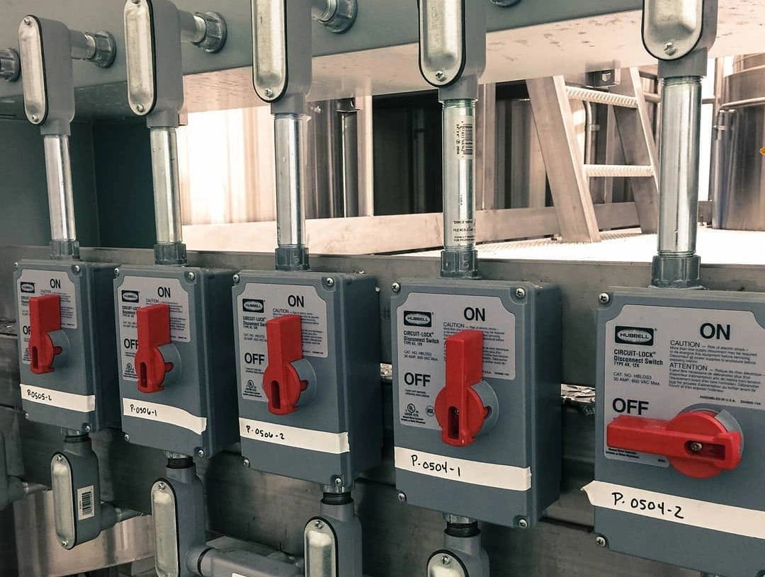
A cam lock disconnect switch works well in machines requiring local manual switching. Common applications include machine tools, pumps, conveyors, generators, and control cabinets. Manual transfer systems can also use rotary mechanisms for source selection. Industrial equipment often benefits from clear physical feedback at the control panel. Operators can see the handle position without interpreting software screens. Maintenance teams can identify the local isolation point more quickly. Some designs support padlocking in the off position for controlled maintenance procedures. The exact safety function depends on product construction and applicable regulations. A Disconnector Lock can provide additional mechanical control when compatible with the switch design. Buyers should verify locking dimensions before selecting an accessory. Environmental protection also matters for outdoor or washdown installations. Suitable enclosure ratings help protect contacts from dust, moisture, and mechanical contamination.
What Real Applications Show The Value Of Rotary Switching?
Real industrial applications demonstrate how rotary switching can simplify equipment control. Kraus & Naimer has reported applications involving power control equipment at production sites. One reported example involved inverter replacement for outdoor drainage pumps. The company reported an 80% reduction in labor for that replacement process. Another manual transfer application reportedly reduced introduction costs by 30%. The same material reported wiring labor falling to one-fifth across 32 broadcasting systems. These figures reflect specific installation designs rather than universal performance claims. However, they demonstrate how simplified switching architectures can reduce wiring and labor. Manual switching can also support bypass and transfer arrangements. Engineers should evaluate the actual load, switching sequence, and environmental conditions before applying similar designs. (iPROS)
How Should Installation Requirements Be Evaluated?
Installation planning should begin before the component reaches the production floor. Panel space must accommodate the body, terminals, handle, and wiring routes. Door thickness can affect front-mounted rotary mechanisms. Cable entry direction can influence terminal accessibility. Installers need enough clearance to tighten terminals without stressing conductors. Heat from nearby components may increase the local operating temperature. Outdoor equipment may require suitable enclosure protection against moisture and dust. Vibration can also affect mechanical assemblies on continuously operating machinery. Mounting hardware should remain secure under expected mechanical conditions. Wiring diagrams must match the actual terminal numbering. Installation teams should verify isolation procedures before energizing the finished panel. Correct installation preserves the electrical and mechanical performance specified by the manufacturer.
How Does Product Construction Affect Long-Term Reliability?
Long-term reliability depends heavily on contact quality and mechanical consistency. Contact surfaces must withstand repeated electrical and mechanical cycles. Spring pressure must remain stable throughout the expected service life. Cam materials also need suitable wear resistance for repeated rotation. Excessive mechanical play can change switching accuracy over time. Terminal construction influences resistance, heating, and connection stability. Enclosure materials should match surrounding temperature and environmental conditions. Manufacturing consistency becomes especially important for customized switching sequences. Small dimensional errors can alter contact timing or mechanical travel. Quality control should therefore cover electrical and mechanical characteristics. Production samples can reveal problems before larger quantities enter service. Buyers should request test records when equipment carries significant operational consequences.
| Quality Check | Recommended Verification | Potential Risk |
|---|---|---|
| Contact resistance | Measure resistance under specified conditions | Excess heating and voltage drop |
| Mechanical operation | Check handle travel and position retention | Incorrect switching sequence |
| Terminal strength | Verify connection security and torque requirements | Loose connections and overheating |
| Insulation performance | Check insulation against specified requirements | Electrical leakage or breakdown |
| Switching sequence | Compare actual states with approved diagrams | Incorrect circuit operation |
What Should Buyers Ask Suppliers Before Ordering?
Supplier discussions should begin with application data rather than product photographs. Buyers should provide system voltage, load current, phase count, and load type. Motor applications should include motor power and starting conditions when available. The required pole count should also appear in the purchase specification. Switching positions need clear labels and defined contact states. Buyers should specify mounting style and panel cutout dimensions. Environmental requirements should cover temperature, moisture, dust, vibration, and enclosure conditions. Certification requirements should match the destination market and installation standard. Samples provide an opportunity to verify fit and switching behavior. Technical drawings should accompany quotations for customized configurations. Suppliers should confirm lead times and repeat-order consistency. This process makes supplier comparison more objective and reduces specification gaps.
How Can Correct Selection Reduce Maintenance Risks?
Correct selection creates a clear boundary between normal operation and maintenance isolation. Operators can use defined handle positions to control equipment consistently. Maintenance personnel can identify the intended isolation point without tracing complex control logic. Proper pole selection can also prevent unwanted energized conductors. Mechanical position indicators provide immediate visual feedback at the panel. Locking provisions can support site-specific maintenance procedures when properly designed. However, the switch must still match applicable safety requirements. Upstream protective devices remain essential for fault protection. Installation teams should verify absence of voltage using approved procedures. The disconnect mechanism cannot replace the complete lockout process. A correctly specified device provides one important part of that process. Reliable mechanical switching can therefore support safer and more predictable maintenance routines.
Why Is Specification Accuracy More Important Than Appearance?
Two rotary switches can look almost identical while serving different electrical duties. Their internal contact arrangements may differ significantly. One model may suit resistive loads but lack suitable motor switching capability. Another may provide the correct current rating but use the wrong pole configuration. Mounting dimensions can also vary between visually similar products. These differences become costly when a panel reaches final assembly. Engineers should therefore prioritize technical documentation over appearance. Switching diagrams reveal internal behavior that photographs cannot show. Rated values establish operating boundaries for the component. Mechanical drawings confirm whether the device will physically fit. Certification documents provide additional evidence for regulated applications. This specification-first approach reduces substitution errors during procurement. It also supports consistent performance when equipment requires repeat production.
How Can Buyers Build A Reliable Procurement Specification?
A strong procurement specification combines electrical, mechanical, environmental, and documentation requirements. Start with supply voltage and maximum operating current. Add the load category and expected switching frequency. Define the number of poles and every required switching position. Specify maintained, spring-return, or momentary action where applicable. Include the required mounting method and panel dimensions. Environmental conditions should cover temperature, humidity, dust, and vibration. Locking requirements should identify the required handle position and accessory type. Certification needs should reflect the destination market and installation environment. Request a technical drawing before approving the final purchase. Production samples should match the approved configuration before volume manufacturing. Finally, retain the approved specification for future repeat orders. This method creates a clear technical reference for engineering, purchasing, and quality teams.