Why Is An Earth Fault Indicator Test Important?
An earth fault indicator test ensures reliable grid monitoring, preventing unexpected outages and maximizing substation equipment uptime.
Essential Objectives of an Earth Fault Indicator Test
Power distribution networks require continuous monitoring to prevent catastrophic system failures. Electrical engineers deploy specialized sensors to detect abnormal current flows instantly. Conducting a regular earth fault indicator test helps maintenance crews identify grid vulnerabilities. These diagnostic procedures verify that protective relays respond correctly during ground faults. Modern substations use a Cable Type Short Circuit Grounding Flash Fault Indicator to secure medium-voltage networks. This device measures zero-sequence magnetic fields to pinpoint precise failure locations. Without routine validation, aging sensors might fail to report critical system alerts. Failure to detect these anomalies leads to severe equipment damage and prolonged outages. Thus, utilities must establish rigorous testing schedules to maintain absolute operational safety. Technical managers prioritize these evaluations to guarantee continuous electricity delivery to industrial clients. Reliable grids depend on the accurate performance of every single sensor in the field.


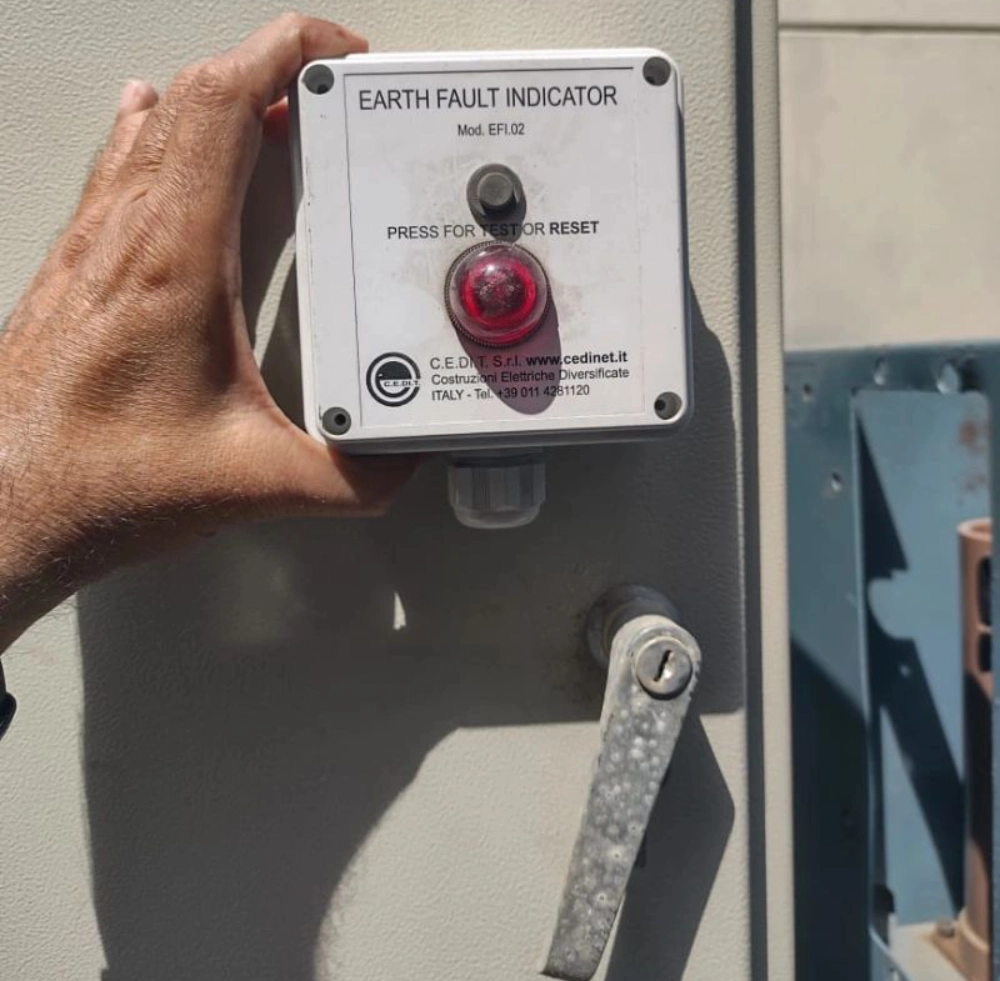
Execution Protocols for an Earth Fault Indicator Test
Testing protocols vary based on the specific design of the installed monitoring equipment. For instance, operators frequently inspect a Panel mounted Paddle Type Short circuit Fault Indicator. This mechanical device utilizes physical flags to show fault conditions on local control switchboards. Technicians apply synthetic current signals to simulate overcurrent events during the physical calibration. They verify the optical and mechanical reset mechanisms to ensure operational readiness. Any delay in the flag deployment indicates internal spring fatigue or dust accumulation. Field teams must clean the mechanical linkages to restore optimal response times. Regular calibration prevents false alarms caused by minor network fluctuations or harmless transients. System operators record these diagnostic parameters to track device health over several years. Accurate record-keeping ensures timely replacement of failing sensor units before major storms arrive.
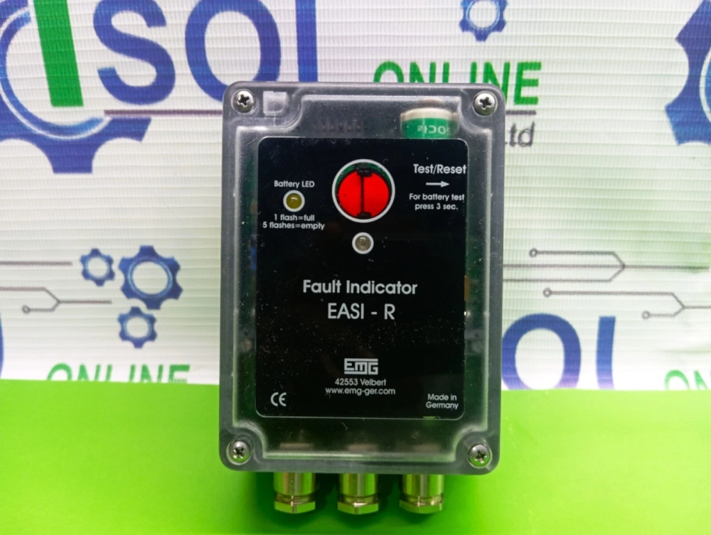
Technical Parameters of Ground Fault Indicator Sensors
Industrial engineers compare diverse diagnostic instruments to select the most reliable grid sensors. Different sensor models exhibit unique response profiles under varying environmental temperatures. We examine these performance characteristics in the comprehensive data chart below. The comparison highlights crucial operating thresholds, communication protocols, and physical housing ratings. Engineers evaluate these variables to match specific devices with local substation demands. Some systems require rugged outdoor enclosures with IP67 ingress protection ratings. Other indoor installations benefit from compact modular footprints to fit inside narrow cabinets. Analyzing these technical specifications enables utility managers to build highly resilient networks. Selecting correct hardware minimizes emergency maintenance costs over the system lifecycle. The following table displays raw performance metrics gathered from standardized laboratory evaluations.
| Sensor Model | Current Range | Reset Mode | Enclosure Rating |
|---|---|---|---|
| Overhead Line Type | 10A - 1000A | Automatic / Timed | IP68 Weatherproof |
| Busbar Type | 20A - 1200A | Manual push-button | IP40 Indoor |
| Ring Main Unit Type | 5A - 600A | Remote SCADA signal | IP65 Dustproof |
Data Interpretation of Sensor Performance Tables
The detailed table above illustrates how operational parameters differ across major sensor categories. Weatherproof overhead line units tolerate broad current spikes up to one thousand amperes. In contrast, indoor busbar units feature manual reset buttons for localized safety management. Remote main units integrate directly with supervisory control systems using cellular telemetry channels. These features allow grid supervisors to choose appropriate equipment for harsh physical environments. Substation design teams prioritize higher enclosure ratings for coastal distribution assets. They implement secondary reset options in remote regions to reduce manual site visits. This mechanical customization prevents unexpected system downtime during extreme weather occurrences. Utility operators rely on these robust parameters to ensure continuous power grid reliability. Every specific metric supports targeted maintenance strategies to maximize overall system efficiency.
Sequential Ground Fault Detector Verification Protocol
Field testing requires a systematic sequence to verify both electrical and mechanical functions. Technicians execute an earth fault indicator test to avoid skipping vital safety checks during field tasks. The list below outlines the precise calibration steps required for modern indicator devices. Each action item corresponds to an industrial standard for high-voltage protection equipment. Operators use specialized calibration tools to apply precise simulated electrical loads. They observe physical indicators to confirm correct visual and digital flag behaviors. These verified procedures minimize human error during complex substation maintenance routines. Adhering to strict validation protocols ensures consistent device accuracy under real operating loads. Furthermore, proper sequencing prevents accidental damage to fragile microprocessors in the field. Maintenance managers require written confirmation of every step before system reactivation occurs.
- De-energize the local feeder line to establish a safe working environment.
- Inspect physical wire connections for signs of thermal corrosion or loose terminals.
- Inject a low-voltage test signal into the primary sensor coil.
- Record the exact response time of the local LED visual indicators.
- Verify that the remote auxiliary contacts transmit fault signals to SCADA.
- Perform a manual mechanical reset to clear the simulated diagnostic flags.

Analysis of Calibration Step Sequencing
Executing these steps in the correct order ensures the safety of grid personnel. De-energizing the local distribution feeder eliminates high-voltage hazards during the testing process. Technicians inspect terminal contacts next to prevent measurement errors from loose wiring. Injecting small current loads mimics real-world fault conditions to trigger the internal logic. They capture accurate signal latency metrics to ensure the sensors operate within legal parameters. Verifying the telemetry signals confirms that remote monitoring stations receive correct alert data. Finally, clearing the indicator flags prepares the local device for standard daily operation. This methodical sequence identifies hidden component defects without risking damage to live grids. Engineers evaluate these baseline results to schedule future maintenance tasks more effectively. Consistent field practices build robust operational databases for future network infrastructure planning.
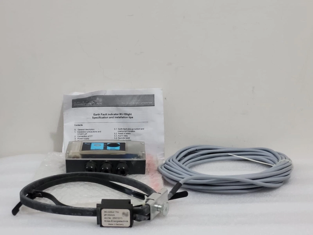
Earth Leakage Sensor Calibration Equipment Specifications
Maintenance crews select professional testing equipment based on specific accuracy requirements. These specialized kits deliver precise current injections to mimic severe short circuit conditions. The secondary comparison chart below shows the dynamic hardware performance metrics. We compare primary calibration kit types, input voltages, output frequencies, and portability scores. Technicians analyze these parameters to choose convenient field tools for remote substations. Lightweight battery-powered units offer superior mobility in mountainous or rural geographic areas. Heavy-duty trolley systems provide high current capacities for massive industrial transmission lines. Selecting the appropriate calibration unit ensures maximum precision during critical field evaluations. Incorrect tester selection may compromise diagnostic outcomes and damage sensitive sensor circuits. The upcoming comparative layout provides clear facts on professional testing hardware capacities.
| Tester Class | Max Current Output | Weight Class | Power Source |
|---|---|---|---|
| Portable Handheld Kit | 50 Amperes | Under 5 Kilograms | Internal Lithium Battery |
| Standard Field Case | 200 Amperes | 15 Kilograms | 110V / 220V AC Utility |
| Heavy Duty Injection Rig | 1000 Amperes | 45 Kilograms | Three-Phase Generator |
Interpretation of Hardware Capacity Data
The detailed hardware table highlights the physical trade-offs between unit power and field mobility. Portable handheld testers deliver fifty amperes of current using internal lithium-ion batteries. These lightweight devices prove ideal for quick inspections in tight residential areas. Conversely, standard field cases require external alternating current power sources to function. They offer higher capacities up to two hundred amperes for general commercial substation applications. Heavy-duty injection rigs generate one thousand amperes to test thick transmission line setups. These large systems weigh forty-five kilograms and require vehicle transport to active sites. Utility organizations balance these characteristics when upgrading their field testing inventories. Purchasing multiple tester types ensures that crews can handle any unexpected technical emergency. Optimal equipment selection directly increases worker productivity and decreases total downtime.

FAQ
How Frequently Should Grid Maintenance Crews Perform This Protection Diagnostic?
Grid maintenance departments must perform an earth fault indicator test at least once every twelve months. Coastal substations often require semi-annual diagnostics because aggressive saltwater corrosion accelerates structural aging. Highly sensitive industrial zones also benefit from frequent scheduled checks to prevent minor distribution faults from stopping production lines. Regular field inspections verify that old internal battery packs retain sufficient charge to operate visual alarm flags. Technicians record the precise baseline values after each trial to identify gradual electronic drift before failures occur. This proactive frequency guarantees optimal protection and maintains high service standards across municipal networks.