Why Use A Voltage Detecting Indicating System Manufacturer?
Voltage detecting indicating system manufacturer for reliable sensing, OEM integration, testing, and medium-voltage switchgear applications.
What Does a Voltage Detecting Indicating System Do?
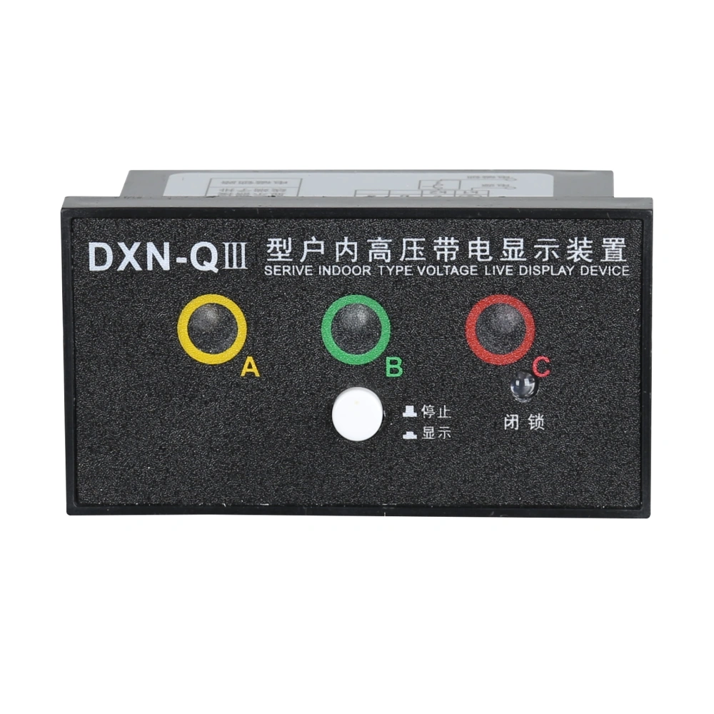
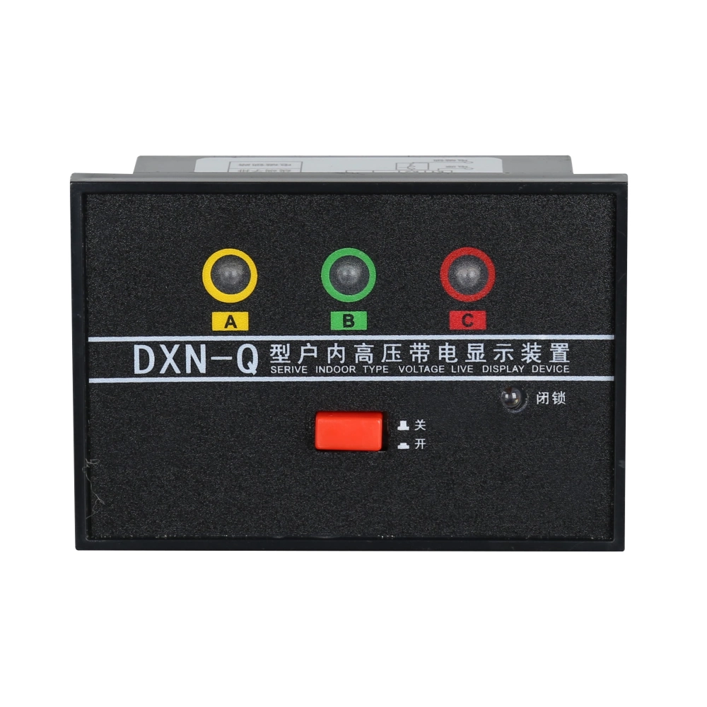
A voltage detecting indicating system manufacturer develops equipment that identifies voltage presence inside switchgear. These systems commonly connect capacitive sensors with visual indicator units. Their purpose is to provide a clear electrical status before switching or maintenance activities. Capacitive sensing detects voltage without creating direct conductive contact with the monitored circuit. The sensing element transfers a controlled signal toward the indicator circuit. An indicator then displays a visible status when the signal reaches its operating threshold. Such equipment supports operational awareness during routine switchgear activities. However, voltage indication does not replace approved isolation and verification procedures. Engineers must match the system with the switchgear voltage class and frequency. Installation conditions also affect sensing performance and long-term reliability. Correct component selection therefore matters throughout the complete electrical design.
Why Choose a Voltage Detecting Indicating System Manufacturer?
A specialized voltage detecting indicating system manufacturer can coordinate sensing components with the complete switchgear structure. This approach helps engineers address electrical and mechanical requirements together. Cabinet space often creates challenges for sensors, terminals, cables, and indicator modules. Manufacturers can review these constraints before production begins. OEM projects may also require customized dimensions, connector positions, labels, or mounting arrangements. Early engineering communication can prevent repeated cabinet modifications during assembly. Suppliers can provide drawings and technical specifications for sample approval. Production teams can then compare finished units against approved configurations. Testing procedures can also remain consistent across repeated batches. Buyers should evaluate documentation, engineering support, and production controls alongside product specifications. Such cooperation can simplify procurement for projects requiring repeated switchgear configurations.
How Does Voltage Detection Improve Switchgear Safety?
Voltage indication gives operators a visible reference about electrical conditions inside switchgear. This information can support switching activities and maintenance preparation. A sensing circuit detects electrical potential through an engineered coupling arrangement. The indicator converts the detected signal into an easily visible status. Detection thresholds require careful selection because voltage conditions vary between applications. Incorrect thresholds may create unclear indications during normal operation. Connection quality also affects the signal reaching the indicator module. Engineers therefore need to consider wiring paths, terminals, insulation, and sensor placement. Environmental conditions can further influence insulation surfaces and connection reliability. Operators must still follow formal isolation and verification procedures before working on equipment. The indication system functions as an additional operational control rather than a standalone safety measure. Proper integration can improve visibility without changing established electrical safety responsibilities.
Which Components Affect Detection Accuracy?
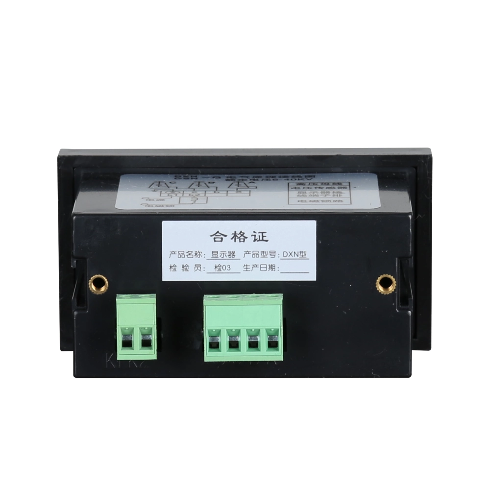
Several components influence how consistently a voltage indication system detects electrical conditions. Capacitive sensors create the interface between energized conductors and the detection circuit. Their capacitance characteristics affect the signal available for subsequent processing. Coupling components transfer a controlled electrical signal toward the indicator. Indicator modules must interpret that signal within their specified operating range. Connecting wires can also affect signal integrity when routing becomes unsuitable. Terminal blocks require secure mechanical connections and appropriate insulation properties. Engineers should additionally confirm the network frequency and expected voltage variation. Sensor placement matters because cabinet geometry can influence electrical coupling. Temperature may also affect electronic components and connection characteristics. Manufacturers should therefore evaluate the complete detection path rather than one individual component. Consistent specifications help maintain repeatable performance across different production batches.
What Standards Should the System Follow?
Relevant standards provide technical requirements for high-voltage switchgear and related equipment. IEC 62271 covers high-voltage switchgear and controlgear across multiple equipment categories. The applicable requirements depend on the equipment type and intended installation. Manufacturers should identify the relevant standard edition during project specification. Verification may involve insulation performance, functional operation, construction, and electrical testing. Buyers should request documentation showing which requirements apply to the supplied configuration. Certification details also require careful review because different certificates can cover different products. A compliant component still needs correct integration into the complete switchgear assembly. Engineers should therefore evaluate both component documentation and final equipment requirements. Standards should support engineering decisions rather than serve as simple procurement checkboxes. Clear documentation also allows different suppliers to be compared using consistent technical criteria.
How Should Manufacturers Handle Different Voltage Ratings?
Rated voltage directly influences the electrical design of sensing and indicating equipment. Higher voltage classes require greater attention to insulation coordination and physical spacing. Electrical clearance describes the shortest distance through air between conductive parts. Creepage distance describes the shortest surface path between conductive parts. Both dimensions matter when contamination or moisture affects insulating surfaces. Sensor construction must also withstand the electrical stress expected inside the switchgear. Indicator circuits require suitable separation from accessible components and other conductive structures. Frequency can influence capacitive sensing behavior and therefore needs confirmation during specification. Manufacturers should evaluate these factors against actual network conditions. Products designed for one voltage class should not automatically serve another class. Drawings should identify rated voltage, frequency, dimensions, and connection details clearly. These specifications help engineers avoid unsuitable substitutions during switchgear production.
What Customization Options Matter for OEM Projects?
OEM switchgear projects often need more than standard voltage indication components. Cabinet designers may have limited panel space or predetermined mounting locations. Indicator dimensions can therefore affect the arrangement of the complete operating panel. Terminal positions may also need adjustment to match existing wiring layouts. Some projects require customized sensing cables because internal cabinet structures differ. Others may need specific labels, connectors, or indicator arrangements. A voltage detecting indicating system manufacturer can review these requirements before production. Engineering teams can then approve drawings before sample units enter assembly. Prototype evaluation can reveal interference with barriers, doors, busbars, or other components. Production should follow the approved configuration and revision number. Documented changes can prevent outdated specifications from reaching later production batches. This process becomes especially valuable when OEM projects involve recurring orders.
How Can Testing Verify System Reliability?
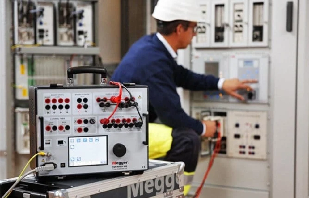
Testing should verify electrical performance and mechanical consistency before shipment. Functional tests can confirm indicator response under specified operating conditions. Insulation tests can evaluate separation between relevant circuits and accessible components. Manufacturers can also inspect terminals, cable connections, housing dimensions, and indicator visibility. Each test should use documented procedures and defined acceptance criteria. Additional sample testing may support projects with demanding validation requirements. Engineers should verify that indicators remain readable from normal operating positions. Mechanical inspection also matters because loose connections can cause intermittent signals. Environmental testing may become necessary when equipment faces temperature or humidity variations. Test records provide useful evidence during commissioning and later troubleshooting. A voltage detecting indicating system manufacturer should maintain traceable production and inspection records. Such records connect engineering specifications with measurable manufacturing results.
What Can a Real Switchgear Project Reveal?
A practical example involves a medium-voltage switchgear project requiring voltage status indication for outgoing feeders. The cabinet offered limited space behind its front operating panel. Engineers selected compact sensing components and a front-mounted indicator arrangement. During prototype assembly, one cable route interfered with an internal insulating barrier. The supplier reviewed the layout and changed the cable position. Engineers then confirmed that the revised route maintained required electrical spacing. Functional tests checked indicator response across the specified operating voltage range. Repeated switching simulations produced consistent visual indications during testing. Final inspection also verified terminal security and indicator visibility. The issue could have caused assembly delays during mass production. Early technical coordination resolved the problem before larger quantities entered manufacturing. This example shows how supplier engineering support can affect practical switchgear integration.
How Does Installation Design Affect Long-Term Performance?
Installation conditions can influence voltage indication performance throughout equipment service life. Switchgear interiors may experience temperature changes, condensation, dust, vibration, or contamination. Moisture can reduce surface insulation performance when contaminants accumulate around connection points. Cable routing should avoid unnecessary proximity to high-stress conductive areas. Terminals require secure fastening to prevent intermittent contact during vibration. Indicator modules should remain accessible for inspection and potential replacement. Mounting hardware must maintain the intended component position over time. Cabinet ventilation can also affect temperatures around electronic indicator components. Engineers should consider these conditions during the original enclosure layout. Maintenance personnel benefit when terminals and indicators remain easy to inspect. A voltage detecting indicating system manufacturer can provide installation requirements based on product construction. Proper installation then helps maintain the intended electrical and mechanical performance.
How Can A Voltage Detecting Indicating System Manufacturer Be Compared?
Buyers can compare suppliers by examining technical capability and production controls. Product appearance alone cannot demonstrate sensing accuracy or long-term reliability. Procurement teams should verify the following points before approving a supplier:
- Confirm rated voltage and operating frequency.
- Check detection thresholds and sensing principles.
- Review sensor compatibility with the switchgear.
- Verify mounting dimensions and terminal positions.
- Request factory testing and inspection documentation.
- Confirm OEM and ODM engineering capabilities.
- Review sample approval and revision procedures.
- Check technical support for installation issues.
These checks connect procurement decisions with measurable engineering requirements. Technical documents should define electrical parameters using consistent units. Sample products can then be compared with approved drawings before volume production. Buyers should also confirm how engineering changes receive formal approval. Clear documentation reduces misunderstandings between purchasing and engineering teams. A structured comparison also helps maintain consistency across repeated switchgear projects.
Which Technical Parameters Should Buyers Confirm?
Technical parameters should receive confirmation before manufacturers finalize production drawings. Rated voltage determines the electrical stress that sensing components must withstand. Frequency affects capacitive sensing behavior and should match the intended power network. Detection thresholds determine when the indicator changes its displayed status. Mounting dimensions must match available cabinet space and existing structural features. Terminal types should correspond with the switchgear wiring design. Environmental requirements may also affect housing materials and insulation arrangements. The following table summarizes important procurement parameters for project specification.
| Parameter | What Buyers Should Confirm | Why It Matters |
|---|---|---|
| Rated Voltage | System voltage and applicable voltage class | Defines electrical design and insulation requirements |
| Frequency | 50 Hz, 60 Hz, or project-specific value | Influences sensing circuit behavior |
| Detection Method | Capacitive or other specified sensing principle | Determines signal generation and system compatibility |
| Detection Threshold | Specified response range | Controls voltage status indication |
| Mounting Method | Panel, bracket, rail, or cabinet-specific mounting | Ensures mechanical compatibility |
| Interface | Terminal, connector, or cable arrangement | Supports correct electrical integration |
| Testing | Functional and insulation test requirements | Provides production quality verification |
These parameters should form part of the approved technical specification. Engineers can use them to verify samples before releasing volume orders. Procurement teams can also compare supplier quotations against identical requirements. This method reduces differences caused by incomplete product descriptions. Clear parameters further simplify communication between cabinet designers and manufacturers. Project records should preserve the final approved configuration for future production. Such documentation becomes particularly useful when the same switchgear design enters repeated manufacturing cycles.
Why Does Manufacturer Support Matter After Delivery?
Technical support can remain important after voltage indication equipment reaches the switchgear factory. Integrators may encounter unexpected clearance or wiring issues during cabinet assembly. Prompt engineering feedback can help determine whether the issue involves installation or configuration. Replacement components may also need to match specifications from the original production batch. Consistent records make this process easier for maintenance and procurement teams. Manufacturers should retain relevant drawings, revision information, and production specifications. Troubleshooting assistance can help distinguish indicator faults from upstream electrical problems. Clear installation information can also reduce unnecessary component replacement. Long-term OEM projects benefit from consistent technical communication across different orders. This continuity becomes valuable when equipment remains operational for many years. Reliable supplier support therefore extends beyond shipping and initial product delivery.
FAQ
Can a Voltage Detecting Indicating System Replace Manual Testing?
A voltage detecting indicating system cannot replace approved electrical verification procedures. Its primary function involves showing voltage status through a designed sensing circuit. Manual testing uses suitable instruments and established procedures to confirm electrical conditions. These methods serve different purposes within a complete electrical safety process.
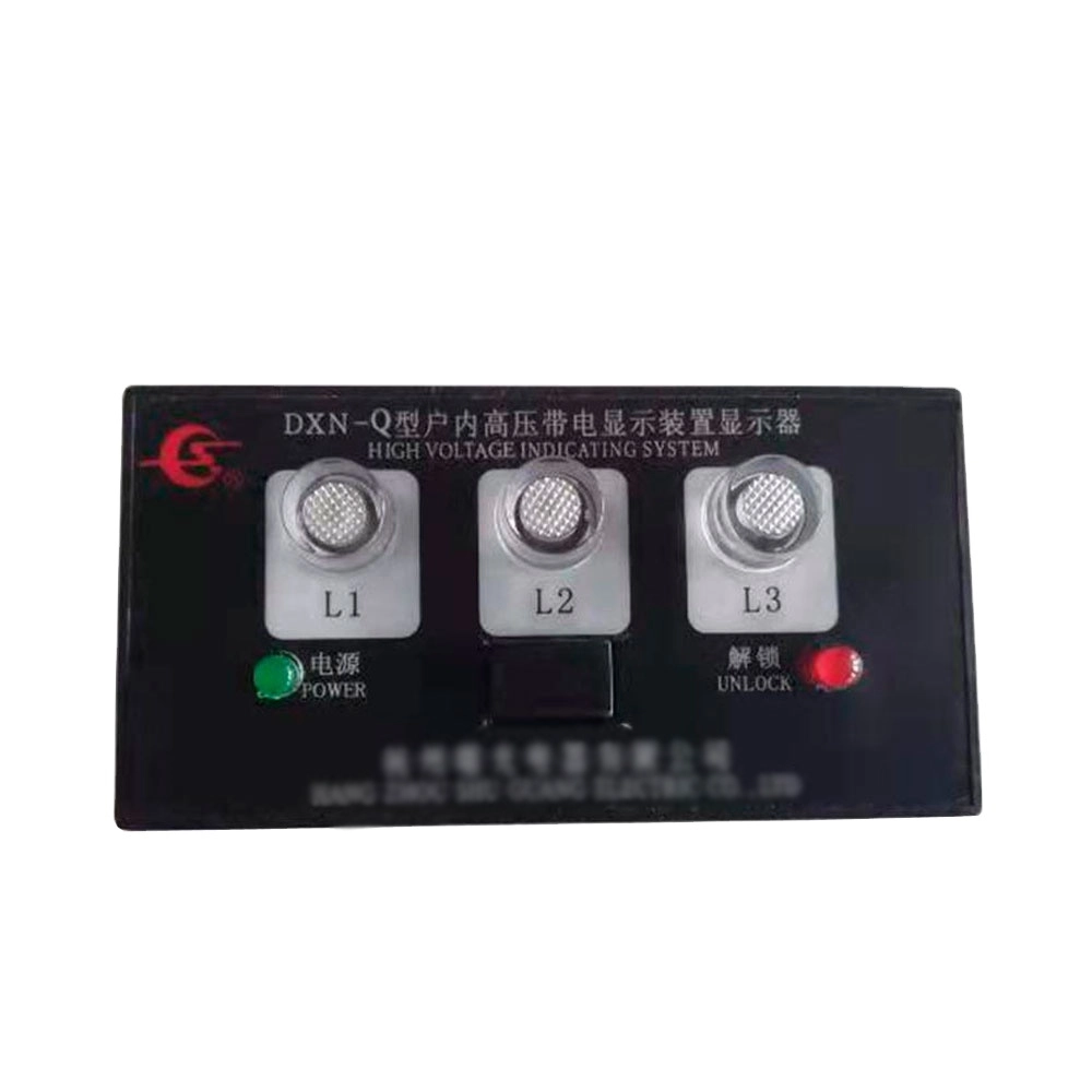
An indicator may show voltage presence according to its specified detection threshold. However, operators still need to follow isolation, lockout, and verification requirements. Faults within sensing components can also affect the displayed indication. Regular inspection can identify damaged cables, terminals, sensors, or indicator modules. Site procedures should define how operators interpret indicator status during maintenance. Manufacturers can provide technical specifications, but qualified personnel remain responsible for safe operation. Keeping indication and verification functions separate reduces the risk of incorrect reliance.
Where Are Voltage Detecting Indicating Systems Commonly Used?
Voltage detecting indicating systems commonly appear inside medium-voltage switchgear and distribution equipment. Typical applications include feeder panels, ring main units, and compact substations. They can also provide voltage status indication around switching compartments.
Each application creates different electrical, mechanical, and environmental requirements. Compact equipment may prioritize small sensors and short connection paths. Larger switchgear can accommodate separate indicator assemblies with additional installation space. Outdoor equipment may require stronger consideration of moisture and environmental exposure. Indoor equipment can still experience condensation or contamination under unsuitable conditions. Engineers should therefore match the sensing arrangement with actual operating conditions. Rated voltage, frequency, enclosure design, and maintenance access all affect system selection. Project specifications should identify these factors before production begins.
What Should Buyers Ask Before Ordering?
Buyers should confirm the complete technical configuration before placing production orders. Important questions should cover voltage rating, frequency, detection threshold, and sensing method. Installation drawings should identify dimensions, terminals, mounting points, and cable arrangements. Buyers should also request information about applicable standards and factory testing. OEM projects need clear confirmation of customization limits and approval procedures. Sample evaluation can verify compatibility with cabinet barriers, doors, busbars, and wiring paths. Procurement teams should record approved technical revisions within the purchase documentation. Environmental conditions should also be stated when humidity or contamination may affect operation. After-sales requirements should cover troubleshooting, replacement components, and technical documentation. A voltage detecting indicating system manufacturer should provide information that supports these technical checks. Clear specifications give engineering and purchasing teams a shared reference.