Electromagnetic Interlock For Switchgear Supplier: What Matters?
Electromagnetic interlock for switchgear supplier selection covers voltage, interlocking logic, testing, customization, and documents.
Why Electromagnetic Interlock For Switchgear Supplier Selection Matters
Choosing an electromagnetic interlock for switchgear supplier involves more than checking product dimensions. The interlock must match the switchgear's operating sequence and control circuit. It may control access, switching actions, or mechanical movement between operating positions. Incorrect matching can create unsafe operating conditions or prevent normal maintenance. IEC 62271-200 covers AC metal-enclosed switchgear above 1 kV and up to 52 kV. Its requirements address interlocks and locking devices within applicable switchgear assemblies. A suitable supplier should provide technical information before production begins. Buyers should examine control voltage, mechanical interfaces, contact arrangements, installation space, and environmental conditions. These details determine whether the device works correctly after installation. Supplier communication also affects testing, documentation, and future replacement requirements.
What Does an Electromagnetic Interlock Actually Control?
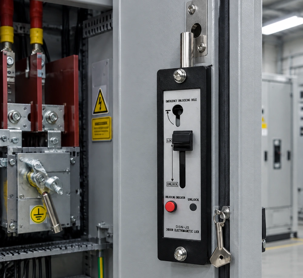
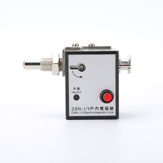
An electromagnetic interlock uses an energized or de-energized control circuit to permit or restrict a mechanical action. The lock usually contains a coil, moving armature, locking mechanism, terminals, and mounting structure. Depending on the design, energizing the coil can release the locking element. Another configuration may hold the mechanism under different electrical conditions. The actual logic depends on the switchgear sequence and project requirements. For example, access to a compartment may require a verified electrical condition before release. A switching mechanism may also require another device to reach a defined position first. IEC requirements address interlocks that prevent switching operations, access to operating interfaces, or insertion and withdrawal of removable parts. Therefore, buyers should define the required operating sequence before selecting the lock.
Which Switchgear Conditions Should the Interlock Monitor?
A reliable interlocking scheme starts with clearly defined equipment states. Typical signals can include circuit-breaker position, disconnector position, earthing-switch position, door status, and voltage presence. Each signal should have a defined relationship with the permitted mechanical action. Consider a medium-voltage feeder cabinet with a removable circuit breaker. The breaker should reach the required open position before withdrawal becomes possible. A product such as DSN-JK Active Electromagnetic Lock for Switchgear can support defined mechanical release conditions within such an interlocking sequence. The sequence should also prevent unsafe switching combinations. IEC 62271-200 addresses these operational restrictions for applicable switchgear assemblies. In one documented substation modernization project, engineers used different interlocking methods across legacy and upgraded equipment. New-zone interlocking used digital communication, while legacy signals remained hardwired. This example shows why a supplier must understand the complete control architecture.
What Should an Electromagnetic Interlock For Switchgear Supplier Provide?
Technical documentation should describe every parameter needed for engineering approval. Electrical data should include rated control voltage, operating current, contact capacity, insulation requirements, and terminal configuration. Mechanical data should identify overall dimensions, mounting holes, locking direction, and available locking travel. The supplier should also specify operating temperature and relevant environmental limitations. Buyers should request dimensional drawings instead of relying on product photographs. A drawing can reveal conflicts with busbar supports, wiring channels, door mechanisms, or existing brackets. Contact diagrams are equally important because a lock may provide auxiliary contacts for status feedback. These contacts can connect with relay inputs or control circuits. Suppliers should also identify whether the lock supports normally open or normally closed auxiliary arrangements. Clear specifications reduce modification work during panel assembly and commissioning.
How Do Voltage and Control Circuits Affect Interlock Design?
Control voltage is one of the first electrical parameters that buyers should confirm. Common projects may use different DC or AC auxiliary supplies. The selected coil must match the available voltage and operating conditions. A mismatch can cause insufficient actuation, overheating, or failure to release. Control circuit design also determines how the interlock behaves during power loss. Engineers should define whether the required condition is locked or released when the coil loses power. That decision affects operational safety and system behavior. A documented 22 kV substation study illustrates the importance of separating control equipment and switchgear functions. The tested system included different AC and DC supplies for protection and switching equipment. Buyers should therefore provide complete control voltage information before requesting samples. Suppliers can then verify coil selection and terminal arrangements accurately.
How Should Environmental Requirements Shape Supplier Choice?
Operating conditions can significantly affect electromagnetic lock reliability. Temperature changes influence coil resistance and mechanical movement. High humidity can accelerate corrosion on exposed metal components. Dust can interfere with moving parts when protection is insufficient. Outdoor installations may also require stronger protection against moisture and contamination. Material selection should therefore match the installation environment. Stainless steel or treated steel can provide better corrosion resistance in demanding locations. Internal insulation also deserves attention because electromagnetic components contain conductive and insulating parts. A documented investigation of an electromagnetic lock in a high-voltage substation found insulation problems associated with
What Should You Check About Mechanical Compatibility?
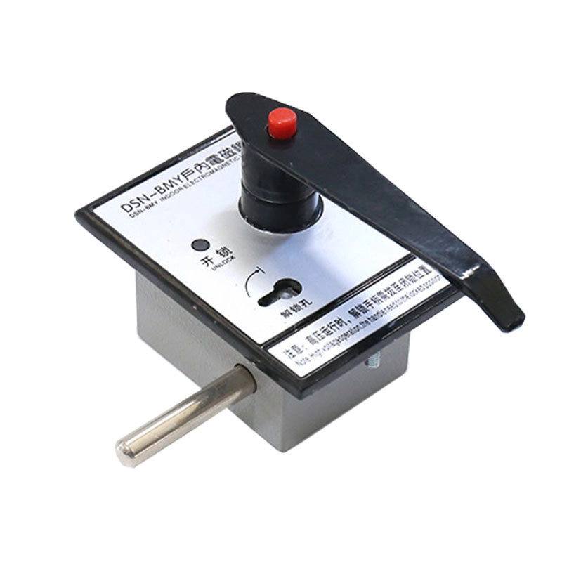
Mechanical compatibility determines whether the lock can perform its intended function after installation. Buyers should confirm mounting-hole spacing, body dimensions, locking-bar position, and available movement. Door thickness and mechanism clearance can also affect installation. For indoor cabinet access applications, DSN DM Indoor Electromagnetic Door Lock also requires appropriate door dimensions and mounting clearance. The locking element must engage securely without excessive mechanical force. Excessive force may indicate poor alignment between the lock and the controlled mechanism. Insufficient travel may leave the mechanism partly engaged. A practical procurement process should therefore include dimensional drawings and physical samples. The sample can be installed on a representative panel before mass production. Engineers can then check movement, clearance, wiring access, and manual operation. IEC 62271-200 includes testing provisions for mechanical and electromechanical interlocks. Mechanical verification should therefore accompany electrical testing.
Which Testing and Quality Documents Should Suppliers Offer?
A qualified electromagnetic interlock for switchgear supplier should provide documents that support engineering review and quality control. The package may include product drawings, wiring diagrams, specifications, inspection records, and test reports. Material information can also help when the installation has corrosion or insulation requirements. Factory testing should verify electrical operation and mechanical movement against approved specifications. Repeated operation can help identify sticking, inconsistent release, or excessive mechanical wear. The supplier should also document the tested control voltage and operating conditions.For switchgear assemblies, the interlock should be considered within the complete operating sequence.
IEC 62271-200 specifies requirements for applicable metal-enclosed switchgear and includes provisions concerning interlocks and locking devices. Buyers should avoid accepting generic test documents when the supplied configuration differs from the approved design.
How Can Buyers Compare Electromagnetic Interlock For Switchgear Supplier Capabilities?
Supplier comparison should focus on documented technical capability rather than appearance alone. A lower unit price does not compensate for incompatible dimensions or incomplete technical information. Buyers can use the following matrix during technical evaluation.
| Evaluation Item | What to Confirm | Why It Matters |
|---|---|---|
| Control voltage | AC or DC value and tolerance | Ensures correct coil operation |
| Mechanical interface | Dimensions, mounting holes, locking travel | Prevents installation conflicts |
| Auxiliary contacts | Contact type, rating, terminal arrangement | Supports status monitoring |
| Operating sequence | Locking and release conditions | Matches the switchgear logic |
| Environment | Temperature, humidity, corrosion conditions | Supports long-term reliability |
| Documentation | Drawings, diagrams, test records | Supports approval and inspection |
| Customization | Special dimensions and control requirements | Supports non-standard applications |
The comparison should continue beyond the initial quotation. Buyers should check whether the supplier can answer engineering questions with specific data. Technical drawings should correspond with the quoted configuration. Test records should also match the same product version. This approach helps identify gaps before purchase orders reach production. A documented switchgear modernization project demonstrates the value of this principle. Engineers retained hardwired interlocking across a legacy boundary instead of forcing incompatible control architectures together. Such decisions depend on accurate technical information rather than catalog descriptions. Supplier evaluation should therefore measure engineering responsiveness alongside product specifications. A technically suitable product still requires correct integration into the complete switchgear system.
What Questions Should You Ask Before Ordering?
A structured question list can prevent many avoidable procurement problems. Buyers should confirm the following points before approving a production order.
- What control voltage does the electromagnetic coil require?
- Does the lock support the required AC or DC circuit?
- What are the exact mounting dimensions?
- What locking travel and direction does the mechanism require?
- Which switchgear states permit release?
- Which conditions must keep the mechanism locked?
- Are auxiliary contacts required for position feedback?
- What contact ratings and terminal arrangements are available?
- What environmental conditions can the lock withstand?
- Which drawings and test documents will accompany the shipment?
- Can the supplier provide a representative sample?
- Can customized dimensions or mounting structures be produced?
These questions connect product selection with actual switchgear operation. They also create a common technical reference for purchasing and engineering teams. The supplier can use the answers to confirm configuration before manufacturing. Engineering teams can compare the approved design against installation drawings. Quality teams can then inspect the delivered product using the same requirements. This process becomes particularly important when a project combines new and existing switchgear. Legacy equipment may use hardwired logic, while newer equipment may use communication-based interlocking. A supplier should know which interface the lock must serve. Clear requirements therefore reduce the risk of redesign during assembly, commissioning, or field installation.
Why Technical Communication Matters After Supplier Selection
Technical communication remains important after the supplier has been selected. Project teams should confirm drawings before releasing production quantities. Changes to mounting holes, coil voltage, or contact configuration can affect the complete control system. Even a small dimensional change may interfere with a door mechanism or internal wiring. Engineering approval should therefore cover the final product configuration. Sample testing provides another useful checkpoint before mass production. During testing, technicians can verify locking, release, manual operation, and electrical feedback. They can also inspect wiring terminals and physical clearances. Interlocking should never replace formal lockout and tagging procedures during maintenance. Proper communication between the project team and an electromagnetic interlock for switchgear supplier keeps the interlock within its intended role.
How Does Customization Affect Switchgear Interlock Projects?
Customization becomes useful when standard dimensions cannot fit the switchgear mechanism. Typical changes may involve mounting plates, body dimensions, locking-bar geometry, coil voltage, or auxiliary contacts. However, customization should begin with engineering data rather than appearance. The supplier needs accurate drawings of the controlled mechanism and surrounding installation area. Photographs can support communication, but they cannot replace dimensional drawings. The required switching sequence should also accompany the mechanical information. This approach allows the supplier to evaluate both physical and electrical compatibility. A transformer-room application described in a technical patent used an electromagnetic lock within a control circuit. The design allowed access only when the associated high-voltage equipment met the defined non-energized condition. Such applications show why customization must follow the actual safety sequence. Functional requirements should remain the primary reference during product development.
How Should a Supplier Support Long-Term Replacement Needs?
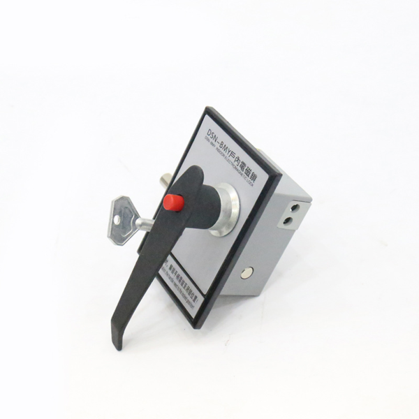
Long-term support matters because switchgear installations can remain operational for many years. Replacement planning becomes difficult when the original product lacks clear identification and technical records. Suppliers should maintain stable product specifications and revision information. Each customized configuration should have an identifiable drawing or model reference. Replacement units should match the original coil characteristics and mechanical interface. Buyers should also retain wiring diagrams and approved dimensional drawings. These documents can help maintenance teams identify suitable replacements later. A supplier with engineering support can also assist when the switchgear design changes during refurbishment. Modernization projects often combine legacy components with new control equipment. One documented brownfield project retained hardwired interlocking across a legacy boundary while using digital interlocking within the upgraded zone. This illustrates the value of interface-specific engineering. Long-term compatibility depends on records, configuration control, and clear technical communication.