How Can An Indoor Interlocking Electromagnet Manufacturer Help?
Indoor interlocking electromagnet manufacturer supports switchgear safety, OEM customization, testing, and reliable cabinet integration.
How Does An Indoor Interlocking Electromagnet Improve Switchgear Safety?
An indoor interlocking electromagnet manufacturer supports safer switching sequences inside electrical cabinets. The device prevents selected operations until required conditions are satisfied. This function matters in medium-voltage switchgear with multiple switching components. Typical equipment includes circuit breakers, disconnectors, earthing switches, and compartment doors. An electromagnetic lock adds controlled blocking to mechanical operating mechanisms. Control voltage determines whether the locking element permits or prevents movement. Proper coordination also reduces the chance of incorrect switching sequences. IEC 62271-200 covers metal-enclosed switchgear above 1 kV through 52 kV. Its scope includes both indoor and outdoor installations. A suitable design therefore needs more than a correctly sized coil. Engineers must match mechanical travel, control logic, mounting space, and operating sequence.
How Does An Indoor Electromagnetic Interlock Work?
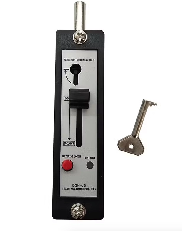
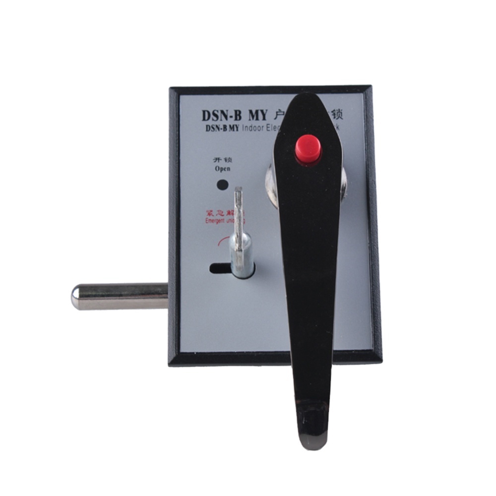
An electromagnetic interlock normally combines a coil, magnetic core, spring, plunger, and locking mechanism. The coil creates magnetic force when the control circuit receives voltage. That force moves the plunger against a defined spring load. Depending on the design, energizing or de-energizing the coil can release the lock. The selected logic should match the cabinet safety philosophy. Auxiliary contacts can also provide electrical feedback to the control system. Engineers can then verify whether the locking mechanism has reached its intended position. Mechanical travel must remain consistent throughout the operating cycle. Excessive friction can increase coil load and delay release. Poor alignment may also cause incomplete engagement. Therefore, dimensional accuracy matters as much as electrical performance during switchgear integration.
Which Switchgear Applications Require Electromagnetic Interlocking?
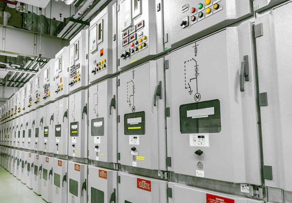
Medium-voltage switchgear often uses interlocks between components that could create unsafe operating conditions. Common examples include circuit breakers, disconnectors, earthing switches, and access doors. A typical sequence prevents an operator from closing an earthing switch while an energized circuit remains connected. Another sequence can prevent a compartment door from opening before the switching device reaches a safe position. Published switchgear documentation shows interlocks controlling breaker position, racking position, doors, and earthing switches. An indoor interlocking electromagnet manufacturer can adapt the locking point to these operating relationships. The application may require one lock or several coordinated units. Engineers should define every permitted and prohibited action before selecting hardware. This approach connects the electromagnetic device with the complete switching sequence.
Which Technical Parameters Should Buyers Compare?
Buyers should evaluate electrical, mechanical, environmental, and installation parameters together. Coil voltage must match the available control supply without exceeding its permitted tolerance. Holding force must also suit the mechanical resistance of the controlled mechanism. Stroke length determines whether the locking pin fully engages or retracts. Mounting dimensions affect cabinet layout and service access. Operating temperature can influence coil resistance and magnetic force. Insulation requirements also depend on the device location inside the cabinet. Buyers should request dimensional drawings before approving production samples. The following parameters provide a practical starting point for technical comparison.
| Parameter | What To Check | Why It Matters |
|---|---|---|
| Coil Voltage | DC or AC value and tolerance | Ensures reliable electromagnetic action |
| Stroke | Plunger travel and locking depth | Confirms complete mechanical engagement |
| Holding Force | Required mechanical resistance | Prevents unintended release |
| Mounting | Hole pattern and installation direction | Ensures cabinet compatibility |
| Temperature | Operating temperature range | Supports stable coil performance |
| Auxiliary Contact | Contact arrangement and rating | Provides position feedback |
How Should The Electromagnet Match The Cabinet Mechanism?
Mechanical compatibility determines whether an electromagnetic lock will perform reliably after installation. Engineers should first identify the exact movement that requires blocking. The locking pin must align with the mating hole or mechanical stop. Excessive lateral force can increase wear and reduce operating consistency. Installation depth also matters because cabinet structures often provide limited internal clearance. Door-mounted devices require different geometry from mechanism-mounted devices. Cable routing should avoid moving parts and high-temperature components. A manufacturer should review drawings before finalizing mounting dimensions. During sample validation, engineers can check the complete operating sequence rather than testing the lock separately. This process helps identify interference between the lock, linkage, door, and operating handle. A correctly matched device can then support repeatable switching actions without restricting normal maintenance access.
Which Standards Influence Interlocking Design?
IEC 62271 provides an important framework for high-voltage switchgear and controlgear design. IEC 62271-1 establishes common specifications for applicable alternating-current switchgear. IEC 62271-200 specifically covers AC metal-enclosed switchgear above 1 kV through 52 kV. The current consolidated IEC publication includes the 2024 amendment. Interlocking requirements also connect with isolation, operating sequences, and access control. The electromagnetic component itself cannot guarantee complete switchgear compliance. Instead, the complete assembly must satisfy its applicable design and testing requirements. An indoor interlocking electromagnet manufacturer should therefore provide technical data that supports system-level engineering. Buyers should also distinguish component test reports from complete switchgear type-test evidence. This distinction prevents incorrect assumptions about what a single locking device can certify.
How Can Manufacturers Test Interlocking Reliability?
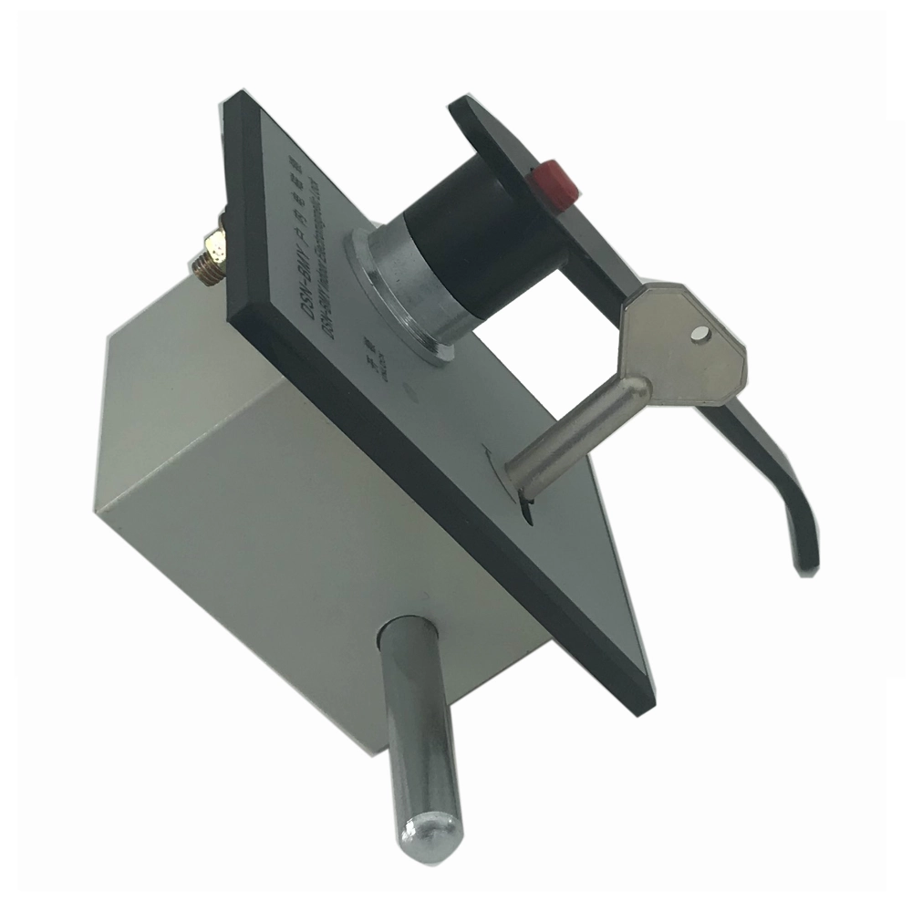
A reliable testing program should verify both electrical behavior and mechanical movement. Coil voltage testing confirms operation across the specified control range. Repeated cycling checks whether the plunger maintains consistent movement after many operations. Holding-force testing verifies resistance against the expected mechanical load. Insulation tests can evaluate electrical separation between conductive parts and accessible surfaces. Temperature testing can reveal performance changes caused by coil heating. Engineers should also inspect return-spring behavior after repeated operation. Auxiliary contacts need separate verification for switching consistency and contact stability. Factory inspection should include dimensional checks because small deviations can affect alignment. A switchgear interlock supplier should retain production records for critical parameters. These records help identify process variation and support traceability during project acceptance.
What Does A Real Switchgear Interlocking Case Show?
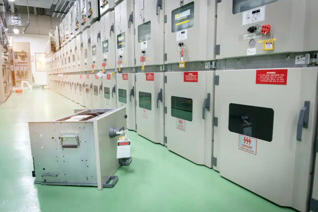
A documented medium-voltage switchgear configuration demonstrates why multiple interlocks must work as one sequence. In one published 27 kV class design, the equipment uses mechanical interlocks to control proper operating sequences. The configuration also separates major switching functions within a metal-clad enclosure. Consider a similar indoor lineup containing a circuit breaker, withdrawable mechanism, and earthing switch. The control sequence can require the breaker to open before withdrawal begins. Earthing operation can then remain blocked until the equipment reaches its disconnected position. This arrangement prevents one action from creating an unsafe state for another component. The following example summarizes the operating relationship without relying on a specific commercial product.
| Operating Condition | Permitted Action | Blocked Action |
|---|---|---|
| Breaker Closed | Normal energized operation | Breaker withdrawal |
| Breaker Open | Prepare for withdrawal | Unsafe sequence requiring closed breaker |
| Disconnected Position | Earthing operation | Actions requiring connected position |
| Earthing Switch Closed | Safe maintenance access | Re-energizing sequence |
Why Does Sequence Verification Matter During Installation?
The case shows that an electromagnetic lock cannot work correctly when treated as an isolated component. Each locking action must correspond with the actual cabinet mechanism. Engineers should test every permitted and blocked sequence after installation. They should also verify the lock under normal control voltage conditions. A loss-of-power scenario deserves separate attention because different designs use different fail-safe philosophies. Some applications keep the mechanism locked when control power disappears. Others require release under defined emergency conditions. The selected behavior must follow the equipment's safety logic and project specifications. Published technical documentation for indoor switchgear also describes electromagnetic blocking coils that keep selected functions locked under loss of supply. Consequently, commissioning should test both energized and de-energized states before equipment enters service.
What Customization Can An Indoor Interlocking Electromagnet Manufacturer Provide?
Customization usually begins with the cabinet drawing and operating sequence. Coil voltage can be selected to match the control circuit. Mounting holes can also be adjusted for existing cabinet structures. Engineers may specify different plunger directions, strokes, spring forces, and locking depths. Auxiliary contacts can provide status signals for control circuits or monitoring systems. Compact housings can help when the mechanism compartment has limited space. For OEM projects, an indoor interlocking electromagnet manufacturer can configure products around the required installation and control arrangement, including DSN-JK Active Electromagnetic Lock for Switchgear OEM/ODM. Sample units should undergo mechanical fitting before batch production. Buyers should confirm drawings, wiring definitions, tolerances, and inspection criteria together. This process reduces installation changes after mass production begins. It also gives the manufacturer clear technical boundaries for repeatable production.
How Can Buyers Evaluate An Indoor Interlocking Electromagnet Manufacturer?
Buyers should assess technical support, manufacturing consistency, testing capability, and customization experience. A capable manufacturer should review application drawings instead of quoting only from a basic product name. Technical communication should cover coil voltage, locking logic, stroke, force, dimensions, and contacts. Sample approval should include actual cabinet fitting and complete sequence verification. Production controls should maintain consistent plunger movement and mounting dimensions. Quality records should also support inspection and traceability requirements. For door-related applications, DSN DM Indoor Electromagnetic Door Lock OEM/ODM may suit projects requiring coordinated electromagnetic access control. Buyers should request drawings, test data, and sample specifications before confirming a production order. This approach creates a clearer technical basis for supplier comparison. It also reduces the risk of selecting a device that fits electrically but fails mechanically.
FAQ
What Is An Indoor Interlocking Electromagnet Used For?
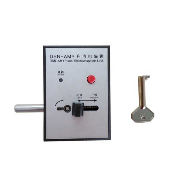
An electromagnetic interlock prevents selected switchgear operations until defined conditions exist. It commonly controls access, switching handles, disconnectors, earthing switches, or breaker mechanisms. The device uses electromagnetic force to move a locking element. That element blocks or releases a mechanical movement based on the control signal. Proper installation can prevent incorrect operating sequences inside medium-voltage cabinets. The exact function depends on the cabinet design and safety philosophy. Some systems lock during power loss, while others follow a specified release sequence. Engineers should therefore define the required behavior before selecting the device. Mechanical alignment, stroke, holding force, and coil voltage also affect reliable operation.
How Do I Select The Correct Electromagnetic Interlock?
Selection should start with the cabinet's operating sequence rather than the product dimensions alone. Confirm the control voltage, current demand, operating mode, stroke, holding force, and mounting arrangement. Next, check available cabinet space and the required locking direction. The plunger must align accurately with the mechanism throughout its complete movement. Temperature, insulation requirements, and auxiliary contact needs should also enter the specification. Buyers should request drawings and samples when dimensions are critical. A sample installation can reveal interference that electrical specifications cannot show. Finally, verify the required testing records and production inspection criteria. This process helps ensure the selected device matches both the electrical control circuit and the mechanical interlocking system.
Can Electromagnetic Interlocks Be Customized For Switchgear?
Yes, many electromagnetic interlocks can be customized for specific switchgear mechanisms. Common customization areas include coil voltage, mounting holes, plunger travel, locking direction, spring force, housing dimensions, and auxiliary contacts. OEM projects may also require special wiring terminals or installation brackets. The manufacturer should first review the cabinet drawing and operating sequence. Engineers can then confirm the required release condition and mechanical interface. Prototype testing should follow before large-scale production. During validation, the device should operate with the actual switchgear mechanism rather than a simplified fixture. Buyers should also confirm dimensional tolerances and inspection requirements before production approval. A documented sample approval process helps maintain consistency between prototype units and later production batches.