How Do You Choose a DSN-J Electromagnetic Lock?
Match a DSN-J Electromagnetic Lock to your grounding switch. Check bolt direction, coil voltage, release logic, and control power loss.
Which DSN-J Model Fits Your Cabinet?
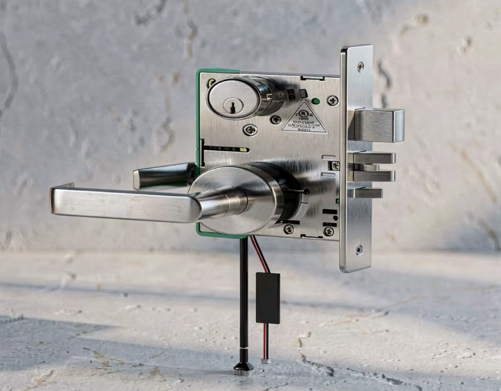
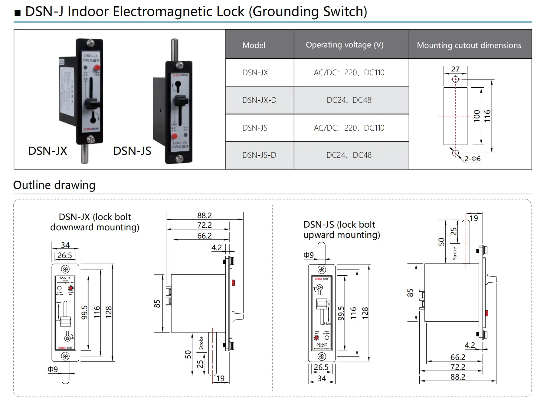
Choose a DSN-J Electromagnetic Lock by matching the bolt direction and auxiliary supply to the cabinet drawing. DSN-JX has a downward bolt, while DSN-JS has an upward bolt. The corresponding -D variants cover the lower DC voltages shown below. Read the bolt direction with the lock in its intended mounting orientation. For a retrofit, compare that orientation with the existing mechanism drawing before selecting a model. Confirm the actual auxiliary supply and the quoted coil rating. In service, the cabinet's interlock circuit determines when the lock can release the grounding switch mechanism.
DSN-J model options and mounting dimensions
| Model | Bolt direction | Operating voltage options | Panel cutout and fixing holes |
|---|---|---|---|
| DSN-JX | Downward | 220 V AC, 220 V DC, 110 V DC |
27 × 100 mm opening Two Ø6 mm holes, 116 mm center to center |
| DSN-JX-D | 24 V DC or 48 V DC | ||
| DSN-JS | Upward | 220 V AC, 220 V DC, 110 V DC | |
| DSN-JS-D | 24 V DC or 48 V DC |
Can You Reuse the Existing Panel Cutout?
Use the DSN-J grounding switch model drawing to compare the opening and fixing holes with the existing panel. Its JX and JS outline views show a 25 mm bolt stroke. Even if the opening and fixing holes align, check where the bolt meets the linkage. Compare the bolt centerline and rear housing depth from the mounting face. Check the available space behind the panel with the bracket and wiring in place. For a replacement, record any offset between the old and proposed mounting positions. Ask the cabinet designer to review any change that would move the bolt relative to the linkage.
How the DSN-J Electromagnetic Lock Releases
Follow the cabinet schematic to identify which conditions allow the coil to operate. Depending on the cabinet design, those conditions may involve disconnector position, breaker position, or other approved signals. Trace each required input to its source contact on the schematic. When the circuit permits release, the coil clears an internal restraint in an electrically released design. The operator can then move the bolt through the documented mechanism action. A release lamp, where fitted, can show permission to unlock. Record which signals indicate permission, bolt position, and grounding switch position. During testing, compare each signal with the physical event that should change it.
Match the Bolt to the Mechanism
Use the lock's mounting face as the reference for bolt projection. Mark the bolt centerline and locate the linkage surface it should block. In the locked position, check how far the bolt engages that surface. Compare the engagement with the cabinet drawing's limits, including bracket position and linkage play. After release, check clearance through the linkage's full travel. The narrowest gap can occur between the end positions. During an approved functional check, note whether the bolt binds at the same point each time. If the coil operates, inspect the bolt and linkage for contact marks or offset. Record the engagement and smallest clearance before accepting the fit.
What to Confirm on the Cabinet Schematic
Check terminal assignments, coil duty, and any position feedback against the cabinet schematic and exact lock documentation. Identify the contacts the cabinet uses to grant permission and those it uses for position feedback. Record each feedback contact's expected state with the bolt locked and released. Check the documented response when control power drops and when it returns. For a proposed DSN-JK active model, review its release conditions and mounting drawing before approving the substitution. Keep the approved order code and drawing revision together for incoming inspection. Those records let the receiving team verify the unit against the agreed configuration.
Test the DSN-J Electromagnetic Lock in Both States
Use the approved commissioning procedure and the switchgear manufacturer's test conditions. For each case, document the starting position, expected permission, and expected bolt movement. Check the inhibited state as well as the permitted state. Observe whether the bolt re-engages when the mechanism returns to its specified position. Include control power interruption and restoration where the procedure calls for them. Where the design provides feedback, log when the contact changes relative to the bolt movement. Record the observed result alongside the expected result. Any mismatch between indicated permission and mechanical response requires investigation before acceptance.
Interlock checks to record during commissioning
| Test condition | What to verify |
|---|---|
| Release conditions unmet | The mechanism remains restrained as the approved sequence requires. |
| Release conditions met | Electrical permission and actual bolt movement agree with the test sheet. |
| Return to the locked state | The bolt re-engages and any specified position feedback agrees. |
| Control supply interruption and restoration | The lock follows the documented response at each starting position. |
Separate Electrical Permission From Mechanical Movement
When a DSN-J Electromagnetic Lock fails to release, record the command, indicator state, and observed bolt position. A missing permission signal calls for a review of the control circuit and its input states. If permission appears, qualified staff can check whether the coil actuates under the approved maintenance procedure. A coil that actuates while the bolt binds directs attention to alignment and linkage clearance. If the bolt travels normally but feedback remains unchanged, review the assigned contact and its wiring. Record the exact point in the sequence where expected and observed behavior first differ. That record helps the team narrow the fault before replacing parts.
Frequently Asked Questions
What happens if the control supply fails?
The result depends on the exact lock design, its starting position, and the cabinet circuit. In an electrically released arrangement, loss of supply can remove the permission needed for a new release. A bolt already in its released position may behave differently. Check the approved operating sequence for both starting positions and for power restoration. Record what the bolt and any feedback contacts should do in each case. If the cabinet provides an emergency release, its use belongs to the site's authorized procedure. Keep that procedure with the cabinet documentation for maintenance teams.
Does the release indicator show that the grounding switch is closed?
A release indicator typically reports permission to operate the lock, according to its wiring. Some cabinets provide separate contacts for bolt position and grounding switch position. Read the schematic to identify the source of each signal and the physical condition it represents. Then compare those signals with the required sequence during approved functional testing. For example, the lamp can show permission before the operator moves the grounding switch. Use the cabinet's designated position indication to confirm the switch state. Follow the site's electrical safety procedure before accessing any compartment.
What should I confirm before ordering a replacement?
Provide the installed model code, nameplate photo, and revision of the cabinet schematic. Identify the auxiliary supply type and voltage, then confirm the coil rating for the quoted variant. Include a drawing that shows bolt direction from a named viewing side. Mark the fixing centers, bolt stroke, and where the bolt engages the mechanism. Ask for terminal assignments and the expected behavior on loss of control power. If the original uses feedback contacts, confirm their function and switching state. Keep the approved drawing with the purchase record for incoming inspection and commissioning.