Medium Voltage Switchgear Interlocking Devices Explained
Medium Voltage Switchgear Interlocking Devices help prevent unsafe switching through proper design, selection, testing, and maintenance.
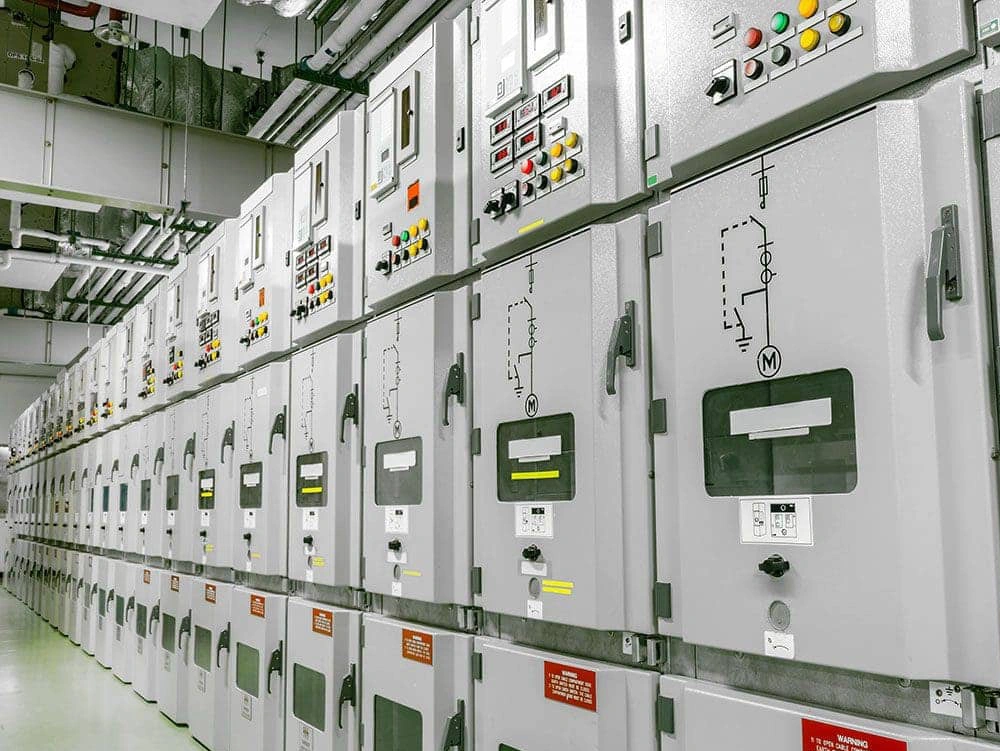
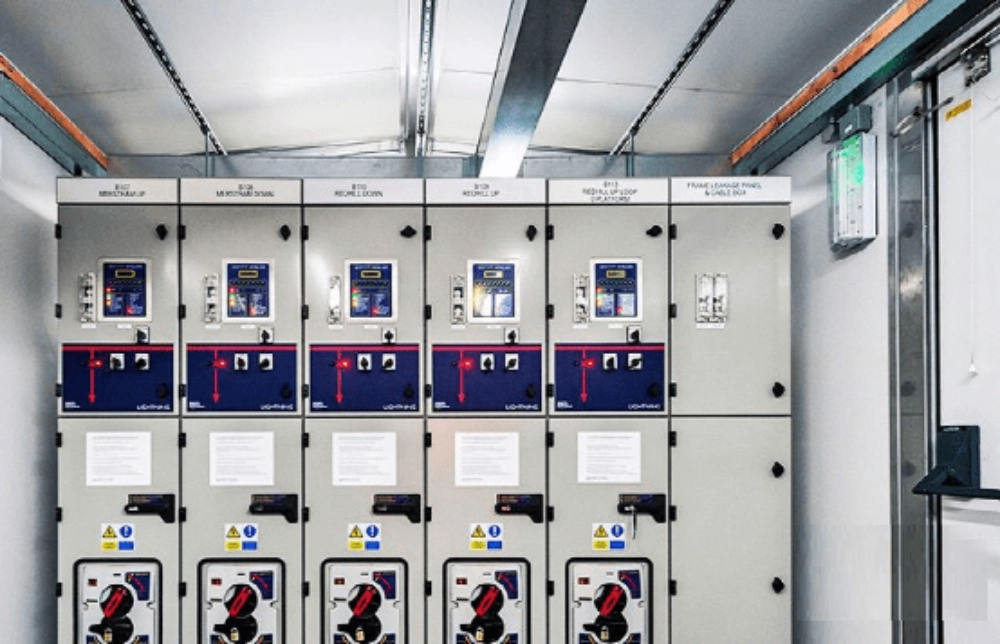
Medium voltage switchgear interlocking devices prevent unsafe switching sequences, incorrect equipment operation, and unauthorized access. They coordinate mechanical mechanisms, electrical control circuits, and access restrictions to support safe operation. Effective interlocking requires more than a suitable locking component. Engineers must also consider equipment positions, operating sequences, control signals, and failure conditions. This article covers common interlocking types, five prevention functions, selection criteria, commissioning tests, and maintenance considerations.
What Are Medium Voltage Switchgear Interlocking Devices?
Medium voltage switchgear interlocking devices restrict specific operations until predefined conditions are satisfied. They may prevent breaker closing in an incorrect position, block unsafe earthing operations, or restrict access to electrical compartments.
Main Components and Functions
Typical systems include mechanical linkages, locking pins, electromagnetic locks, auxiliary contacts, control relays, and position indicators. Mechanical components restrict movement, while electrical circuits provide permissive or blocking signals.
Interlocking supplements protection relays and safe isolation procedures. It does not replace verification that equipment is de-energized or other required electrical safety measures. The complete arrangement must follow the switchgear design and approved operating sequence.
Types of Interlocking Devices Used in MV Switchgear
Different interlocking technologies address different restrictions. Selection depends on the operating mechanism, installation requirements, and required safety functions.
Mechanical, Electrical, and Key Interlocks
Mechanical interlocks use physical components to prevent incompatible movements. They commonly coordinate breaker positions, truck movement, earthing switches, and cabinet doors.
Electrical interlocks use contacts, relays, and control circuits to block operations when required conditions are not satisfied. Their reliability depends on circuit design, contact condition, and accurate position feedback.
Key interlocks enforce predetermined sequences through controlled key release. They are useful when operations involve multiple devices or separate equipment locations. Key management and release conditions must be clearly defined.
Electromagnetic Locking Devices
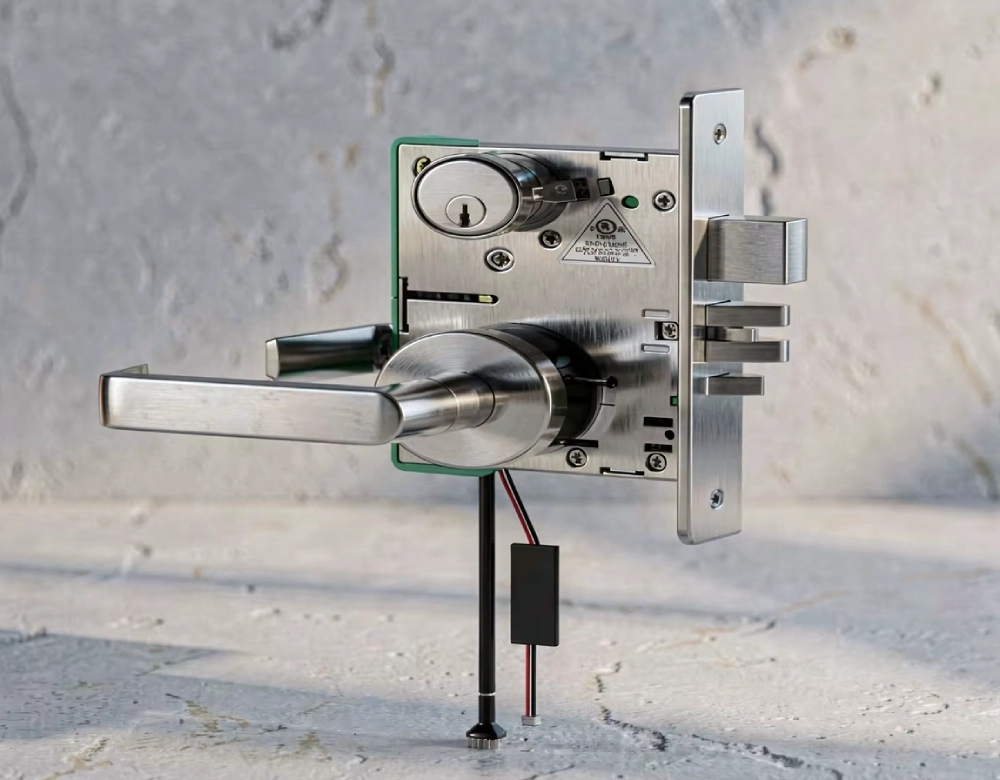
Electromagnetic locks control access or movement through electrically operated locking mechanisms. Depending on the design, they can be used for cabinet doors and selected switchgear operating mechanisms.
For applications requiring an active locking arrangement, the DSN-JK Active Electromagnetic Lock for Switchgear is one option to evaluate. Engineers should confirm its operating voltage, mounting requirements, release conditions, and compatibility with the approved control logic.
No single lock type provides every interlocking function. The selected device must work with the complete switchgear arrangement.
How Do Interlocking Devices Support the Five Prevention Functions?
The five prevention functions address common switching hazards in medium voltage switchgear. Their implementation varies according to the equipment design and applicable requirements.
Preventing Incorrect Switching Under Load
Interlocking can prevent a disconnector from operating until the associated circuit breaker reaches the required position. The system should confirm the actual breaker state rather than relying only on an opening command.
Preventing Breaker Operation in Unsafe Positions
For withdrawable switchgear, interlocking can restrict breaker closing when the truck is between permitted positions. Mechanical restrictions and position contacts help prevent operation outside the approved service or test positions.
Preventing Earthing of an Energized Circuit
The earthing switch must not close when the associated circuit remains energized. Interlocking should enforce the required isolation sequence. Voltage presence indicators provide status information but do not automatically replace approved procedures for verifying de-energization.
Preventing Energization of an Earthed Circuit
Interlocking can block breaker closing while the associated earthing switch remains closed. Reliable position feedback helps ensure that the system responds to the actual equipment state.
Restricting Access to Live Compartments
Door interlocks help prevent access when the required isolation and safety conditions have not been met. A passive electromagnetic lock, such as the DSN-WY-JK Passive Electromagnetic Lock for Switchgear, may be considered when its documented characteristics suit the application.
A locked door alone does not prove that a compartment is safe to enter. Isolation, verification, and earthing must follow the applicable procedures.
How to Design an Interlocking Sequence for MV Switchgear
Interlocking design should begin with the required operating sequence. Engineers must define which actions are permitted, which conditions block them, and how equipment states are confirmed.
Defining and Coordinating Operating Conditions
An interlock matrix can document the required conditions for breaker closing, truck movement, earthing-switch operation, and compartment access. It should identify the relevant mechanical restrictions, electrical contacts, and expected responses.
For example, a breaker closing command may require confirmation that the earthing switch is open and the breaker mechanism occupies an approved position. The exact logic must follow the manufacturer's drawings and project requirements.
Handling Abnormal Conditions
The design should account for conflicting position signals, incomplete mechanical movement, and loss of control power. Engineers must determine how each device behaves under these conditions instead of assuming that power loss automatically creates a safe state.
If the system cannot confirm a required condition, the response should follow the approved safety logic. Operators should never bypass an interlock simply because an operation cannot proceed.
How to Select Interlocking Devices for New and Existing Switchgear
Selecting suitable devices requires both electrical and mechanical compatibility checks.
Checking Technical and Installation Requirements
Confirm the switchgear type, rated voltage, control supply, operating mechanism, mounting dimensions, locking direction, and required travel. For electromagnetic locks, verify the rated coil supply, wiring requirements, release behavior, and mechanical interface.
Environmental conditions and maintenance access should also be considered where relevant. A device that fits physically may still be unsuitable if its operating logic conflicts with the existing interlocking sequence.
Evaluating Retrofit Compatibility
Retrofitting requires reviewing existing drawings, brackets, wiring, auxiliary contacts, and operating clearances. Replacing a lock without checking its release logic or mechanical movement can introduce new conflicts.
Any modification should preserve required safety functions and undergo documented functional testing. Where compatibility is uncertain, obtain confirmation from the switchgear manufacturer or a qualified engineering team.
How to Test and Commission Switchgear Interlocking Devices
Commissioning should verify that the installed system follows the approved interlocking logic. Visual inspection alone cannot confirm that all unsafe operations are blocked.
Functional and Position Tests
Prepare a test plan covering permitted and prohibited operations. Depending on the equipment, this may include breaker closing, truck movement, earthing-switch operation, door access, and position feedback.
Confirm that physical positions match the expected electrical indications and that mechanisms operate correctly. Relevant abnormal conditions should also be tested according to the manufacturer's procedures and site safety requirements.
Documentation and Fault Correction
Record test conditions, expected behavior, actual results, and corrective actions. If an interlock fails, investigate the underlying mechanical, electrical, or configuration problem before returning the equipment to service.
Testing must not depend on forcing mechanisms or bypassing protective functions. Required safety-related tests should pass before the equipment is accepted for operation.
Common Problems with MV Switchgear Interlocking Devices
Interlocking problems can originate in mechanical components, control circuits, position feedback, or system configuration.
Interlocks That Fail to Release
Possible causes include unsatisfied permissive conditions, unavailable control power, mechanical misalignment, and damaged components. Check the approved operating sequence before inspecting the relevant wiring and mechanism.
Never force the lock or apply an unapproved supply to restore operation.
Incorrect Position Feedback
A mismatch between physical position and electrical indication may result from defective contacts, wiring faults, incorrect adjustment, or incomplete movement. The discrepancy must be resolved before relying on the affected interlocking function.
Conflicts After Equipment Modification
Replacement locks, revised wiring, or altered mounting arrangements can change the original operating sequence. Review the interlock matrix and test all affected functions after modification. Update drawings and maintenance records to reflect the final configuration.
Standards and Documentation to Check Before Approval
Interlocking requirements depend on the equipment type, installation, and applicable project standards.
Relevant Standards and Technical Records
IEC 62271-200 covers AC metal-enclosed switchgear and controlgear for rated voltages above 1 kV and up to 52 kV. Engineers should confirm the applicable edition, scope, and project requirements before determining which provisions apply.
Review mechanical drawings, circuit diagrams, interlock matrices, operating instructions, and commissioning records. Compliance cannot be established by checking an individual lock alone; the complete assembly and its required functions must be assessed.
Conclusion
Medium voltage switchgear interlocking devices coordinate mechanical restrictions, electrical signals, and access controls to prevent unsafe operations. Reliable performance depends on appropriate device selection, clear operating logic, accurate position feedback, and systematic commissioning.
Engineers should evaluate technical compatibility, failure behavior, and retrofit requirements before approving a design. Documented testing and regular maintenance help preserve the intended safety functions throughout the switchgear's service life.
FAQs
What Are the Main Types of MV Switchgear Interlocking Devices?
The main types are mechanical interlocks, electrical interlocks, key interlocks, and electromagnetic locking devices. Mechanical designs restrict physical movement, while electrical designs use control circuits to block prohibited operations. Key interlocks enforce sequences through controlled key release. Electromagnetic locks control access or movement at designated positions. These technologies may be combined in one switchgear assembly. The appropriate configuration depends on the equipment design, required safety functions, and approved operating sequence.
Can Electromagnetic Locks Replace Mechanical Interlocks?
Not automatically. Electromagnetic locks and mechanical interlocks may perform different functions within the same assembly. A mechanical interlock can prevent incompatible movements, while an electromagnetic lock may control access or release at a specific location. Any substitution requires checking the operating sequence, failure behavior, mechanical compatibility, and applicable safety requirements. Engineers should review the complete design and validate changes through functional testing rather than assuming that similar-looking devices provide equivalent protection.
What Should Be Tested Before Commissioning Switchgear Interlocks?
Testing should cover all required permitted and prohibited operations in the approved interlock matrix. Relevant checks include breaker position restrictions, truck movement, earthing-switch conditions, door locking, and electrical feedback. Technicians should confirm that actual equipment positions match the expected indications. Applicable abnormal conditions should also be checked according to approved procedures. Record results and corrective actions, and resolve safety-related failures before placing the equipment into service.
What Happens If an Interlocking Device Fails?
A failure may prevent normal operation, produce incorrect position feedback, or compromise a required restriction. Operators should follow site procedures and avoid forcing the mechanism or bypassing the interlock. Qualified technicians should inspect the mechanical parts, control supply, wiring, contacts, and associated logic. If a required safety function is affected, the equipment should remain unavailable for normal operation until the problem is corrected. The affected functions must then be tested before the equipment returns to service.