How Are Auxiliary Contacts Used in Switchgear Locks?
Switchgear electromagnetic lock auxiliary contacts provide status feedback, support interlocking logic, and improve cabinet safety.
How Do Switchgear Electromagnetic Lock Auxiliary Contacts Work?
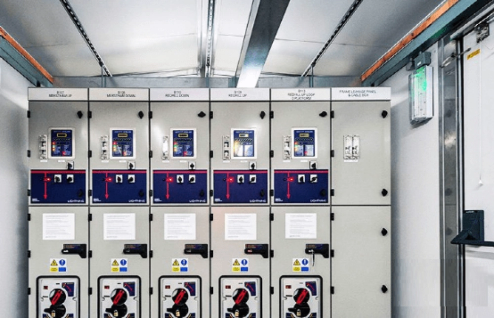
Switchgear electromagnetic lock auxiliary contacts provide electrical feedback about a locking mechanism's operating state. They open or close monitoring circuits when the associated mechanism reaches a defined position. Unlike electromagnetic coils, these contacts do not generate locking force. Instead, they transmit status signals to relays, programmable logic controllers (PLCs), indicator lamps, or alarm circuits. In medium-voltage switchgear, this feedback helps coordinate cabinet access with equipment operating procedures. The signal depends on the contact arrangement and its mechanical connection. Engineers must verify manufacturer drawings before assigning functions to individual terminals. Coil energization alone cannot confirm that a locking pin has reached its intended position.
What Components Make Up an Auxiliary Contact Assembly?
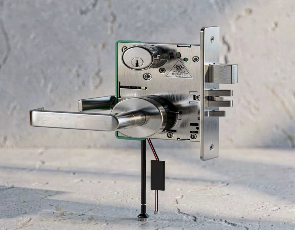
An auxiliary contact assembly typically includes fixed contacts, moving contacts, an actuator, insulated housing, and electrical terminals. The actuator transfers movement from the locking mechanism to the contact elements. When the mechanism reaches a specified position, the moving contact changes its connection with the fixed contact. Spring pressure and contact geometry help maintain electrical continuity during normal operation. Insulating materials separate conductive components and reduce unintended electrical connections. Terminal markings identify available circuits, although numbering conventions can vary between manufacturers. Buyers should confirm the terminal diagram rather than relying on appearance. They should also check mounting dimensions, operating travel, wire access, and insulation requirements before approving a replacement assembly.
How Are Auxiliary Contacts Connected to Switchgear Control Circuits?
Auxiliary contacts connect to monitoring or control circuits through designated terminals. Depending on the application, the receiving device may be a PLC, interposing relay, alarm input, or indicator lamp. The contact provides a switching signal, while the receiving circuit interprets its state according to predefined logic. Before installation, technicians must verify control voltage, switching current, load characteristics, and electrical isolation requirements. They should also confirm whether the circuit uses alternating-current or direct-current control power. Incorrect ratings can cause unreliable signals, excessive contact wear, or electrical damage. A complete wiring diagram should identify the power source, protective devices, terminal connections, and destination of each signal wire.
How Do Auxiliary Contacts Support Electrical Interlocking?
Electrical interlocking coordinates equipment operations by requiring specified conditions before a command proceeds. In switchgear, auxiliary contacts can communicate a locking mechanism's position to a relay or control system. The receiving logic checks whether the reported state matches the conditions required for the next operation. For example, a control sequence may inhibit a command when the expected feedback remains absent. This arrangement reduces dependence on operator assumptions and helps identify incomplete operating sequences. However, electrical interlocking differs from mechanical interlocking, which uses physical components to restrict incompatible movements. Engineers should define the function of each safeguard and assess possible wiring, contact, and mechanical failures. Auxiliary contacts support the interlocking scheme but cannot independently guarantee electrical safety.
How Can Switchgear Electromagnetic Lock Auxiliary Contacts Confirm Lock Status?
Switchgear electromagnetic lock auxiliary contacts provide meaningful feedback only when their mechanical linkage corresponds to the condition being monitored. A properly designed linkage may change contact state when a locking pin reaches its specified position. The control system can then compare that signal with the expected operating sequence. However, a contact connected only to a coil circuit may indicate an electrical command rather than actual mechanical engagement. A damaged linkage, incorrect adjustment, or faulty contact can produce misleading feedback. Engineers should examine the manufacturer's mechanical drawings and verify the switching sequence during commissioning. Where the application requires stronger fault detection, designers may need additional position sensing or independent monitoring.
What Is a Practical Example of Auxiliary Contact Integration?
Consider an illustrative medium-voltage switchgear commissioning scenario involving a cabinet electromagnetic lock. The control panel should indicate when the locking mechanism reaches its designated position, but initial testing produces an incorrect status. Technicians verify the control supply and compare the wiring against the approved schematic. After safely isolating the relevant circuit, they test continuity and inspect the terminal connections. Their checks reveal that the signal wire uses the wrong terminal pair for the intended normally open (NO) logic. The locking mechanism operates correctly, but the control system receives the opposite state. After correcting the connection, technicians repeat the operating tests and confirm the expected feedback. They document the results before accepting the installation.
Which Auxiliary Contact Parameters Should Buyers Compare?
Buyers should compare electrical and mechanical specifications rather than selecting contacts by appearance. Contact configuration determines available signal logic, while rated voltage and current define permissible switching conditions. Electrical ratings may differ between resistive and inductive loads, so engineers must check the applicable load category. Mechanical endurance indicates the expected operating cycles under specified test conditions. Terminal style, wire size, mounting dimensions, and operating travel affect installation compatibility. Buyers should also check temperature limits, insulation requirements, and environmental conditions. The following table summarizes the main selection criteria. These descriptions provide general purchasing guidance rather than specifications for any particular lock model.
| Parameter | What to Verify | Why It Matters |
|---|---|---|
| Contact configuration | NO, NC, or changeover contacts | Determines available signal logic |
| Rated voltage | Specified AC or DC voltage | Prevents electrical overstress |
| Rated current | Switching current and load category | Reduces contact wear and failure |
| Mechanical endurance | Rated operating cycles | Supports service-life assessment |
| Mounting dimensions | Fixing points and clearance | Ensures physical compatibility |
| Terminal arrangement | Terminal numbers and wire access | Reduces installation errors |
| Environmental limits | Temperature and humidity range | Supports reliable operation |
These criteria must match the actual circuit and installation conditions. A contact rated for one load category may not suit another load at the same nominal voltage. Inductive loads can produce switching transients that accelerate contact degradation without suitable suppression. Buyers should request technical data and wiring diagrams before approving substitute components. They should also confirm that the replacement preserves the original actuator travel and switching sequence. A physically compatible contact block may still report the wrong state if its mechanical interface differs. Final selection should follow verified specifications rather than assumptions based on similar dimensions.
How Should Technicians Wire and Test Auxiliary Contacts?
Technicians should follow the approved schematic and the manufacturer's installation instructions. Before handling wiring, qualified personnel must isolate relevant power sources and follow the site's electrical safety procedures. They should identify every terminal and verify the contact configuration before making connections. After installation, continuity testing can confirm whether contacts open and close as expected. Technicians should compare these results with the mechanism's physical movement and the control panel's indications. Testing should cover the specified operating positions and relevant control conditions. Personnel must never assume that a correct indicator proves the switchgear is de-energized. Electrical isolation requires approved procedures and appropriate verification instruments. For reliable commissioning, switchgear electromagnetic lock auxiliary contacts must produce the expected signals throughout the specified operating sequence.
A consistent inspection checklist can help standardize commissioning activities:
- Confirm the model, terminal diagram, and contact configuration.
- Verify control voltage and electrical ratings.
- Inspect wiring, terminal security, and insulation.
- Test NO and NC continuity in specified positions.
- Compare feedback signals with panel indications.
- Verify the intended interlocking response under approved test conditions.
- Record results and resolve discrepancies before acceptance.
Technicians should test the complete signal path rather than checking the contact block alone. Correct continuity at the lock does not guarantee a correct signal at the PLC input. Damaged cables, incorrect common connections, or faulty input channels can interrupt feedback. Commissioning records should document the tested conditions, results, corrective actions, and acceptance status. Any failed safety-related function requires resolution under the site's procedures. Personnel should never bypass a protective interlock merely to clear an alarm or accelerate testing.
What Faults Can Affect Auxiliary Contact Feedback?
Auxiliary contact faults can originate from electrical, mechanical, or installation problems. Loose terminals may create intermittent signals, while damaged insulation can cause unintended connections. Oxidation or contact wear may increase resistance and prevent reliable switching in low-current monitoring circuits. Mechanical misalignment can stop the actuator from reaching its intended travel. Incorrect terminal selection may reverse the expected logic without damaging the hardware. Technicians should investigate these possibilities systematically rather than replacing the complete lock immediately. They should also distinguish contact problems from failed coils, defective relays, and incorrect PLC configurations. A structured diagnostic process reduces unnecessary replacement and helps preserve the intended interlocking logic.
How Can Buyers Specify Auxiliary Contacts for Switchgear Locks?
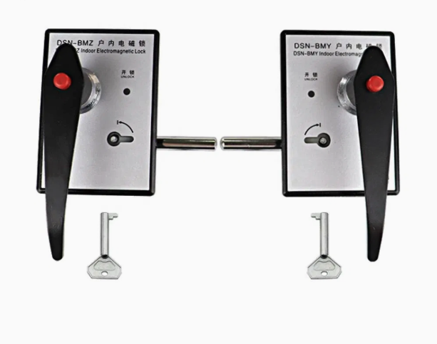
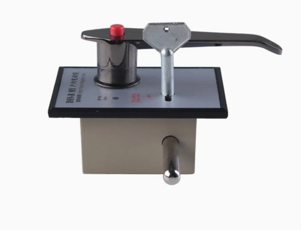
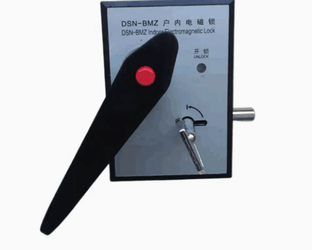
Buyers should provide a complete technical specification when requesting electromagnetic locks with auxiliary contacts. The specification should identify the switchgear application, mounting arrangement, operating voltage, contact configuration, and required feedback function. It should also define the signal destination and receiving circuit characteristics. For retrofit projects, existing cabinet drawings and terminal diagrams help confirm compatibility. Buyers should verify lock dimensions, bolt direction, actuator travel, and available wiring space. They should also confirm whether auxiliary contacts come standard or require a separate option. The DSN DM Indoor Electromagnetic Door Lock is a product designation worth checking for indoor electromagnetic locking applications. Buyers must verify its actual configuration and contact availability through applicable supplier documentation.
How Do Auxiliary Contacts Improve Switchgear Lock Maintenance?
Routine testing helps maintenance teams identify deteriorating contacts and unreliable feedback before these issues disrupt operations. Inspection frequency should reflect manufacturer recommendations, operating cycles, environmental conditions, and site risk assessments. Technicians should check terminal security, wire insulation, actuator movement, and contact-state transitions. They should also review historical fault records for intermittent signals or recurring alignment problems. A contact that works during one test may still fail under vibration or repeated operation. Maintenance procedures should therefore use consistent test conditions and documented acceptance criteria. After servicing, technicians must verify the complete interlocking sequence before returning equipment to service. Records should identify faults, corrective work, and verification results.
What Should Engineers Verify Before Commissioning Auxiliary Contacts?
Commissioning should confirm that installed contacts, wiring, and control logic work together as specified. Engineers should review approved drawings, equipment ratings, and manufacturer instructions before testing begins. They should verify terminal connections and confirm expected contact states for relevant mechanism positions. The control panel must display accurate feedback, while interlocking logic must respond appropriately to valid and invalid signals. Testing should also consider relevant fault conditions and recovery procedures. Any discrepancies require investigation before acceptance. Engineers should confirm that component replacements and wiring changes preserve the original design. Final records should identify test results, outstanding issues, corrective actions, and responsible personnel. Reliable commissioning depends on verified results rather than successful coil energization alone. During final verification, switchgear electromagnetic lock auxiliary contacts must accurately report the states defined by the approved design.
FAQ
Can Auxiliary Contacts Detect Whether an Electromagnetic Lock Is Fully Engaged?
Auxiliary contacts can indicate a defined mechanical position when their actuator connects appropriately to the locking mechanism. However, they cannot automatically confirm complete engagement unless the design establishes that relationship. A contact connected only to a coil circuit may indicate an electrical command rather than actual bolt movement. Engineers should check mechanical drawings and the switching sequence before assigning a safety function. During commissioning, technicians should compare contact transitions with the mechanism's physical position. Where the application requires stronger diagnostic coverage, designers may need additional position sensing or independent monitoring. The complete interlocking arrangement determines what evidence is sufficient for each permitted operation.
Can Auxiliary Contacts Be Connected to a PLC or Alarm Circuit?
Yes, auxiliary contacts can provide inputs to PLCs, indicator circuits, alarms, and suitable control relays. Compatibility depends on rated voltage, switching current, load characteristics, and the receiving device's input requirements. Some PLC inputs require specific voltage ranges or sourcing and sinking arrangements. An interface relay may be necessary when the contact and receiving circuit are incompatible. Engineers should also consider electrical isolation, cable routing, interference, and broken-wire consequences. The wiring diagram must identify the intended logic and expected signal states. Technicians should test the complete path from the lock contact to the final display or control response.
How Often Should Switchgear Lock Auxiliary Contacts Be Tested?
Testing frequency depends on manufacturer recommendations, operating frequency, environmental conditions, and the installation's risk assessment. Sites with frequent operations or harsh conditions may require more frequent inspections than controlled environments with limited operation. Maintenance teams should follow approved procedures and record contact transitions, wiring condition, and intermittent faults. Testing should also follow relevant repairs, wiring changes, or replacement of locking components. A fixed interval cannot suit every installation, so the responsible engineer should establish a suitable schedule. If feedback becomes inconsistent, technicians should investigate promptly rather than waiting for routine maintenance. Functional testing must never replace required electrical isolation or other safety procedures.