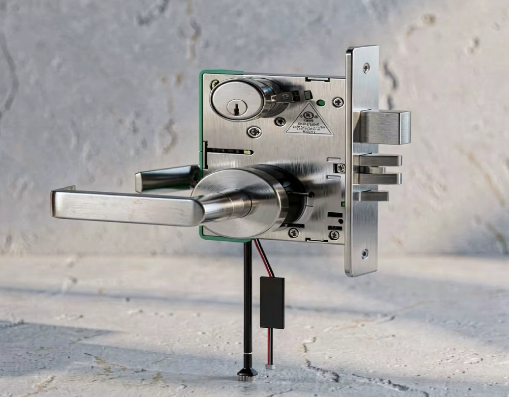
What Dimensions Matter For Switchgear Electromagnetic Locks?
Switchgear electromagnetic lock dimensions affect pin stroke, mounting clearance, cabinet fit, and reliable interlocking performance.

Why Dimensional Accuracy Matters for Electromagnetic Locks
Switchgear electromagnetic lock dimensions directly affect installation compatibility, mechanical interlocking, and operational reliability. An incorrectly sized lock may prevent a cabinet door from closing or stop a locking pin from engaging properly. These problems can compromise interlocking sequences and increase maintenance requirements. Electrical equipment manufacturers must therefore evaluate mechanical dimensions alongside electrical ratings and operating conditions. A suitable selection begins with the available mounting space and the intended locking function. Engineers should also consider neighboring components, wiring routes, and the movement of doors or operating mechanisms. For replacement projects, existing installation drawings provide a useful starting point. However, physical measurements remain necessary when cabinets have undergone modifications. Accurate dimensional verification helps procurement teams avoid unsuitable orders and costly installation adjustments.
What Determines Switchgear Electromagnetic Lock Dimensions?
Several parameters determine whether an electromagnetic lock fits a particular switchgear assembly. The housing length, width, and height establish its external footprint. Mounting-hole spacing determines how the body attaches to a panel or bracket. Locking-pin diameter and stroke influence engagement with the receiving mechanism. Cable outlets and terminal positions also affect installation space. Engineers should distinguish nominal dimensions from functional measurements because both influence compatibility. A compact housing may still require substantial clearance for wiring or moving parts. Similarly, matching external dimensions does not guarantee that two locks share compatible pin geometry. Buyers should request dimensioned drawings before comparing alternatives. These drawings should identify measurement references, mounting coordinates, tolerances, and the position of critical functional components.
How Do Housing Length, Width, and Height Affect Installation?
Housing dimensions determine whether a lock fits within the cabinet's available mounting envelope. Length affects horizontal space, while width influences clearance from adjacent components. Height determines whether the lock interferes with shelves, structural beams, or door-mounted hardware. Cabinet depth also matters when engineers install the lock behind a front panel. A housing that fits the panel opening may still collide with internal wiring ducts. Installation teams should measure the complete available envelope rather than relying on visible surface space. They should also reserve sufficient room for fasteners, electrical terminals, and maintenance access. For example, a replacement lock may match the original housing width but extend farther toward a cable duct. Checking all three dimensions prevents this avoidable interference.
Why Does Mounting-Hole Spacing Matter?
Mounting-hole spacing describes the distance between corresponding hole centers. This measurement determines whether installers can secure the lock without modifying the cabinet or mounting bracket. Engineers should record horizontal and vertical spacing separately when the mounting pattern contains multiple holes. They should also verify hole diameter, thread specifications, and edge distances. Small discrepancies can prevent fasteners from entering correctly or place the housing under mechanical stress. Consider a maintenance team replacing a lock on an existing medium-voltage cabinet. The new unit matches the original housing dimensions, but its mounting holes differ by several millimeters. The team cannot secure it directly without changing the bracket. A dimensioned drawing would reveal this mismatch before procurement. Confirming mounting coordinates therefore reduces retrofit delays and unnecessary fabrication.
How Should Locking-Pin Diameter and Stroke Be Measured?
Locking-pin geometry determines how the electromagnetic lock engages with the cabinet's receiving mechanism. Pin diameter must match the opening and the mechanical tolerances of the associated hardware. Excessive clearance may create unwanted movement, while insufficient clearance can cause binding. Stroke refers to the pin's available travel between its retracted and extended positions. Engineers should confirm both total travel and the required engagement depth. These measurements are not interchangeable because a long stroke does not guarantee sufficient engagement. For example, a pin may extend far enough to reach a receiving hole but enter it only partially. Door movement or bracket misalignment can make the problem worse. Buyers should verify the pin's position, travel direction, and engagement requirements against the complete interlocking assembly.
Which Dimensions Affect Door and Mechanism Alignment?
Correct alignment depends on the relationship between the lock, cabinet door, mounting bracket, and receiving component. Door thickness can affect the mounting arrangement when the lock attaches to a door assembly. Bracket offset determines the lock's position relative to the receiving hole. Hinge wear or door sagging may also shift the engagement point over time. Engineers should inspect the cabinet in its normal closed position before finalizing measurements. They should then verify alignment throughout the intended operating sequence. A lock that engages during an unloaded bench test may bind after installation. This can happen when the door applies pressure against the locking pin. When checking switchgear electromagnetic lock dimensions, engineers should account for door movement and bracket offsets alongside the lock's nominal measurements. Adjustable brackets can accommodate limited positioning differences, but they cannot correct every structural mismatch. Proper alignment checks should precede commissioning.
How Do Different Switchgear Applications Change Dimensional Requirements?
Different switchgear compartments create different space and interlocking constraints. Circuit-breaker compartments may require coordination between access doors and the operating mechanism. Cable compartments can have limited room because terminals, conductors, and cable supports occupy substantial space. Busbar compartments may impose additional restrictions because their internal layouts prioritize electrical insulation and conductor separation. The required locking direction also influences mounting orientation and pin travel. Engineers should identify the exact compartment and intended interlocking sequence before choosing a lock. A lock suitable for one cabinet arrangement may not fit another, even within the same switchgear family. For instance, a side-mounted unit may interfere with a cable duct in one enclosure. A front-mounted configuration could avoid that interference if the design permits it. Application-specific drawings help resolve these differences.
What Electrical and Environmental Clearances Must Be Checked?
Mechanical fit alone cannot establish whether an electromagnetic lock suits an electrical cabinet. Engineers must also examine terminal access, conductor routing, insulation requirements, and the surrounding operating environment. Required electrical clearances depend on the equipment design, rated voltage, insulation system, and applicable standards. Buyers should not apply one universal distance to every switchgear installation. Temperature, humidity, dust, and vibration can also affect component selection and long-term performance. A housing may fit the available space yet obstruct an insulating barrier or reduce maintenance access. Wiring should remain protected against abrasion and interference with moving parts. Engineers should confirm that the lock's supply voltage matches the control circuit. They must also verify current consumption, duty requirements, and any relevant environmental ratings. Final approval should consider mechanical drawings and the cabinet's electrical design together.
How Can Buyers Compare Switchgear Electromagnetic Lock Dimensions?
A structured comparison helps procurement teams evaluate competing configurations consistently. The following table identifies key measurements and explains why each matters. Actual values must come from the supplier's current technical drawing rather than assumptions about a product category.
| Parameter | What to Verify | Why It Matters |
|---|---|---|
| Housing Length | Overall body length | Prevents interference with adjacent components |
| Housing Width | Maximum external width | Confirms lateral installation space |
| Housing Height | Body height and projections | Checks panel and enclosure clearance |
| Mounting-Hole Spacing | Center-to-center coordinates | Ensures bracket compatibility |
| Mounting-Hole Diameter | Hole size and thread details | Confirms fastener compatibility |
| Locking-Pin Diameter | Pin diameter and tolerance | Supports proper mechanical engagement |
| Pin Stroke | Total travel and engagement depth | Confirms the required locking movement |
| Terminal Clearance | Space for wiring and connection | Supports safe installation and maintenance |
How to Interpret Dimensional Differences
When comparing switchgear electromagnetic lock dimensions, buyers should separate critical functional measurements from secondary packaging differences. Housing variations may be acceptable when sufficient space remains around the unit. However, mounting coordinates and locking-pin geometry usually require closer attention. A difference of only a few millimeters can matter when the receiving hole has limited clearance. Procurement teams should also compare measurement tolerances instead of relying exclusively on nominal values. If a supplier provides several drawings, the team should confirm which revision applies to the quoted model. Any proposed dimensional substitution should receive engineering approval before purchase. These checks create a documented basis for comparing suppliers and reduce the risk of unexpected installation changes.
How Can Incorrect Dimensions Cause Installation Problems?
Dimensional errors can produce several recognizable installation failures. An oversized housing may collide with cable ducts or structural supports. Incorrect mounting-hole spacing can prevent secure fastening or force installers to modify a bracket. A locking pin with an unsuitable diameter may bind or move excessively inside its receiving opening. Insufficient stroke can prevent full engagement, even when the lock appears correctly positioned. Misalignment may also cause repeated wear on the pin and receiving mechanism. Consider a cabinet door that closes only when an installer applies additional pressure. The underlying problem may involve bracket offset rather than electrical failure. Repeatedly energizing the lock will not correct a mechanical mismatch. Technicians should inspect mounting positions, pin travel, and receiving-hole alignment before replacing electrical components.
What Should a Dimensional Inspection Checklist Include?
A consistent inspection process helps engineers identify compatibility problems before commissioning. Teams should record the measurements and compare them against approved drawings.
- Measure housing length, width, and height.
- Record mounting-hole centers, diameters, and thread specifications.
- Check locking-pin diameter, travel, and engagement depth.
- Verify bracket offsets and receiving-hole alignment.
- Confirm terminal positions and wiring access.
- Inspect clearances around ducts, barriers, and moving components.
- Compare measured values against the approved drawing revision.
- Test locking and unlocking under the specified operating conditions.
How to Apply the Inspection Checklist
The checklist works best when engineers complete it before ordering and repeat relevant checks after installation. During procurement, they should compare cabinet measurements with the supplier's dimensional drawing. After delivery, incoming inspection can identify differences between the drawing and the actual unit. Installers should then verify alignment and mechanical travel without forcing the locking mechanism. Functional testing must follow the equipment manufacturer's approved procedures. Electrical interlocks should never be bypassed to compensate for dimensional problems. If measurements fall outside specified tolerances, the team should stop installation and request technical clarification. Recording the results also creates a useful reference for future maintenance. This process improves traceability and helps distinguish product defects from cabinet-specific installation issues.

How Can Buyers Confirm Customization Requirements With Suppliers?
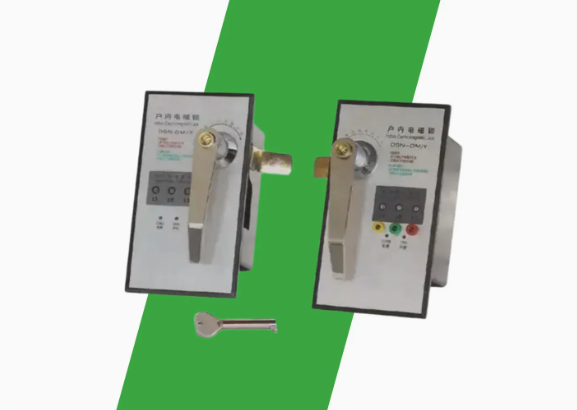
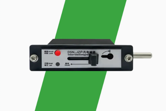
Clear technical communication helps suppliers identify the correct configuration for an existing switchgear assembly. Buyers should provide cabinet drawings, mounting-hole coordinates, available installation space, and photographs where appropriate. They should specify pin diameter, required travel, mounting orientation, supply voltage, and intended interlocking function. A replacement project may involve a legacy medium-voltage cabinet with an undocumented bracket modification. In this situation, engineers should measure the installed arrangement instead of copying an outdated drawing. The supplier can then review the measurements and propose a compatible configuration. For example, a team evaluating a DSN DM Indoor Electromagnetic Door Lock should confirm its actual drawing against the cabinet's mounting pattern. Product naming alone cannot establish dimensional compatibility. Buyers should approve the final drawing and, where necessary, a sample before authorizing bulk production.