How Does Mounting Direction Affect Switchgear Lock Selection?
Switchgear electromagnetic lock mounting direction affects pin alignment, clearance, and reliable switchgear cabinet interlocking systems.
Why Mounting Direction Matters in Switchgear Interlocking
Switchgear electromagnetic lock mounting direction influences mechanical alignment, installation space, and interlocking reliability. Buyers must consider the cabinet structure before selecting a suitable locking mechanism. A lock that fits the available space may still fail if its pin approaches the locking point incorrectly. Horizontal and vertical installations also create different requirements for cable routing and maintenance access. Therefore, procurement teams should evaluate both electrical specifications and mechanical compatibility. The intended interlocking sequence determines how the lock engages with moving cabinet components. Accurate measurements help prevent interference with doors, operating handles, and internal partitions. Engineers should also confirm the manufacturer's permitted installation orientations. These checks reduce modification costs and help maintain reliable operation throughout the switchgear's service life.
How Does Switchgear Electromagnetic Lock Mounting Direction Affect Performance?
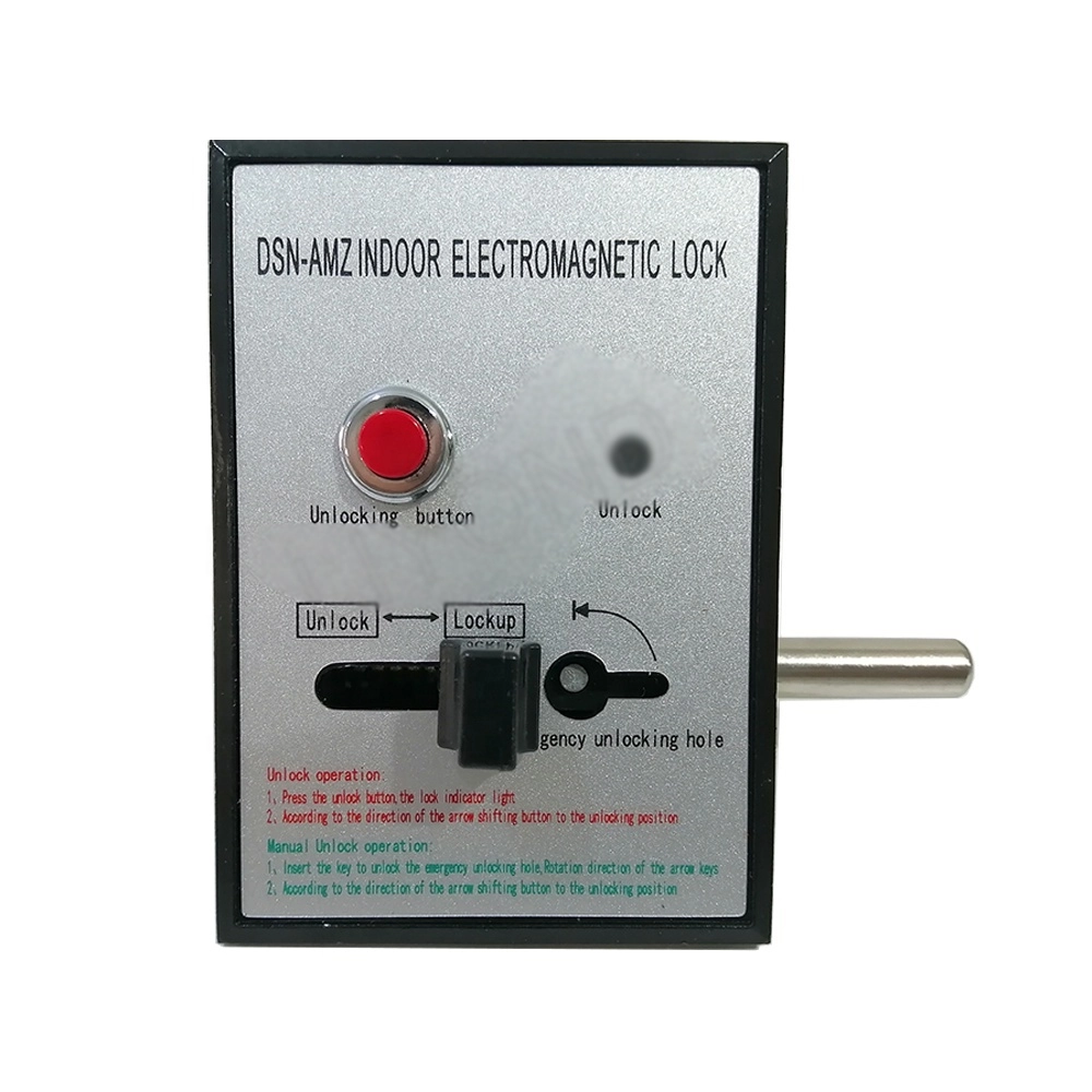
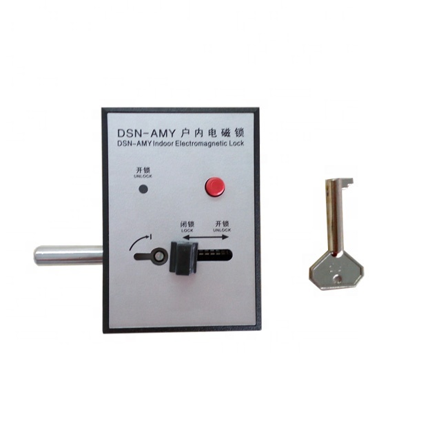
Mounting orientation determines how the locking pin travels toward its engagement point. Electromagnetic actuation moves the internal mechanism according to the lock's design. However, gravity may influence movable components when the manufacturer permits different installation positions. Spring-return mechanisms can also respond differently when friction or misalignment affects their movement. A vertical arrangement may simplify engagement with a vertically moving interlocking component. Conversely, a horizontal arrangement may suit a side-mounted locking point. Neither configuration guarantees better performance without considering the actual mechanism. Engineers should examine the pin's extension direction, return method, and permitted mounting angle. They should also verify the specified operating voltage and duty conditions. Correct orientation supports predictable movement and reduces the likelihood of incomplete engagement.
Which Lock Components Determine the Required Mounting Orientation?
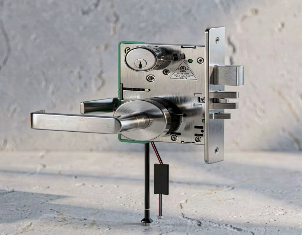
Several internal components determine whether a lock suits a particular cabinet arrangement. The electromagnetic coil generates the magnetic field that actuates the movable iron core. A locking pin transfers this movement to the mechanical interlocking point. Depending on the design, a return spring restores the pin after de-energization. The housing supports these components and establishes the lock's mounting interface. Buyers should inspect how the manufacturer arranges the coil, core, spring, and pin. They should also check whether the pin operates axially or interacts with an external linkage. Side loading can increase friction and interfere with complete engagement. Dimensional drawings should identify the mounting face, pin centerline, travel distance, and fixing holes. These details help engineers match the lock to the cabinet's actual mechanical layout.
How Do Horizontal and Vertical Mounting Configurations Differ?
Horizontal mounting often suits side-facing interlocking points, while vertical mounting can accommodate vertically arranged mechanisms. The best option depends on the cabinet's internal geometry and the lock's approved operating positions. Engineers should assess the pin's travel path before fixing the housing. They must also consider whether nearby hinges, rails, or operating shafts restrict movement. Gravity can affect certain spring-loaded or freely moving components, although the extent depends on their construction. Cable entries may require different routing when installers rotate the housing. Maintenance technicians also need enough room to inspect terminals and remove mounting screws. Buyers should not assume that rotating one model automatically preserves its rated performance. The manufacturer's drawings and installation instructions must confirm compatibility with the proposed orientation.
| Consideration | Horizontal Installation | Vertical Installation |
|---|---|---|
| Typical application | Side-facing locking points | Vertically arranged mechanisms |
| Space assessment | Check lateral clearance | Check upper and lower clearance |
| Pin alignment | Match the horizontal engagement axis | Match the vertical engagement axis |
| Gravity influence | Depends on internal construction | May affect certain moving components |
| Cable routing | Check side access and bend radius | Check terminal access and cable support |
| Final verification | Confirm approved orientation and full pin travel | Confirm approved orientation and full pin travel |
What Cabinet Conditions Influence Electromagnetic Lock Positioning?
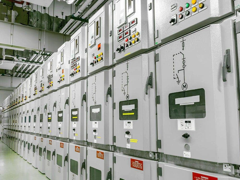
Cabinet conditions often determine the practical mounting position more strongly than the lock's external dimensions. Engineers should identify the door frame, operating shaft, compartment partitions, and existing interlocking hardware. They must also reserve clearance for the locking pin throughout its complete movement. A lock body may fit within the cabinet while its pin collides with a bracket or moving linkage. Temperature, vibration, dust, and moisture can influence material selection and long-term reliability. The specified enclosure protection and operating temperature range should match the installation environment. Electrical clearances and insulation distances also require attention around energized equipment. Installers must route control wiring away from moving mechanisms and sharp edges. A complete cabinet layout helps identify these conflicts before drilling holes or modifying structural parts.
How Can Buyers Verify Mounting Dimensions Before Ordering?
Buyers should obtain a dimensioned drawing before approving a lock for production or replacement. The drawing should show the housing length, width, depth, fixing-hole positions, and mounting-face orientation. Engineers should compare these dimensions with the available cabinet space. Pin diameter, extension distance, and total stroke must match the receiving mechanism. The required engagement depth should also account for tolerances and expected mechanical movement. Where several locks share a cabinet design, procurement teams should confirm whether their mounting interfaces are interchangeable. They should never rely on product photographs to estimate critical dimensions. A physical sample can help validate fit when the assembly has limited clearance. Finally, written confirmation from the supplier should document the permitted orientation and any installation restrictions.
What Are the Main Mounting Direction Selection Criteria?
Procurement teams should compare mechanical requirements before evaluating price or delivery time. The following checklist helps engineers identify compatibility issues early.
- Confirm the permitted mounting orientations in the manufacturer's technical documentation.
- Measure the housing envelope, fixing-hole spacing, and available installation clearance.
- Verify the locking pin's direction, diameter, stroke, and required engagement depth.
- Check rated voltage, coil specifications, control wiring, and operating conditions.
- Inspect the cabinet's interlocking sequence and the position of connected mechanisms.
- Confirm access for installation, inspection, adjustment, and eventual replacement.
- Record the approved mounting position on the final assembly drawing.
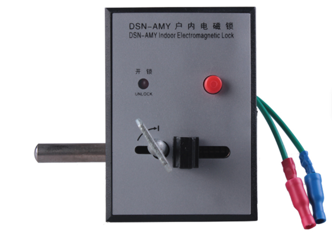
How Do These Selection Criteria Improve Lock Compatibility?
The checklist becomes useful when engineers apply every item to the actual cabinet design. For example, a lock with suitable electrical ratings may still prove mechanically incompatible. A short pin might not reach the receiving component, while excessive travel could cause interference. Incorrect hole spacing may require a redesigned bracket or additional machining. Therefore, switchgear electromagnetic lock mounting direction should form part of the mechanical specification, rather than remain an installation detail. Procurement teams should also distinguish manufacturer-approved mounting positions from orientations that merely appear physically possible. Documented confirmation reduces uncertainty during supplier evaluation. When the cabinet design changes, engineers should reassess alignment and clearances before approving the revised arrangement.
How Can Incorrect Lock Orientation Cause Installation Problems?
Incorrect orientation can create symptoms that resemble electrical failure. A pin may stop before reaching the receiving hole, or it may rub against an edge. Such contact increases friction and can prevent consistent engagement. A return spring may also struggle to restore the mechanism when components bind. Installers should first isolate the equipment according to approved safety procedures. They can then inspect the mounting face, pin centerline, fixing screws, and receiving hardware. Witness marks or uneven wear may indicate repeated contact between misaligned parts. Technicians should compare the installed arrangement with the approved drawing. They should never force the pin or bypass an interlock to compensate for poor alignment. Correcting the underlying geometry usually provides a more reliable solution than modifying the locking mechanism without authorization.
What Can a Real Switchgear Installation Case Teach Buyers?
Consider an illustrative commissioning scenario involving a vertical cabinet interlock and a lock initially positioned horizontally. During a mechanical test, the pin repeatedly contacted the edge of the receiving bracket. The coil operated, but the mechanism did not achieve consistent engagement. The commissioning team isolated the equipment and compared the installation against the cabinet drawing. Their inspection identified a mismatch between the pin axis and the receiving hole. The team revised the mounting arrangement within the manufacturer's approved configuration, then checked the pin's full travel. Subsequent tests confirmed alignment across the specified operating sequence. This scenario illustrates a plausible failure pattern, not a verified customer case. It shows why engineers should validate geometry before commissioning rather than treating every engagement problem as an electrical fault.
How Should Installers Test Lock Operation After Mounting?
Commissioning should verify both electrical actuation and mechanical engagement. First, qualified personnel should confirm the supply voltage against the lock's nameplate and technical specifications. They should inspect terminal connections, cable support, and insulation condition. Next, they should test pin extension and retraction under the manufacturer's prescribed procedure. The pin must move without binding, scraping, or contacting nearby structures. Technicians should then verify engagement with the receiving mechanism throughout the required interlocking sequence. They must confirm that the lock permits only the operations intended by the approved design. Any abnormal noise, incomplete travel, or inconsistent response requires investigation before handover. Testing must follow site safety rules and applicable commissioning procedures. Personnel should never defeat protective interlocks to accelerate testing or demonstrate operation.
How Should Switchgear Electromagnetic Lock Mounting Direction Be Documented?
A procurement specification should describe the required orientation in measurable terms. Engineers should identify the mounting face, pin axis, fixing-hole pattern, and engagement position. They should also reference the approved assembly drawing and the lock's model-specific installation instructions. The phrase switchgear electromagnetic lock mounting direction should appear alongside the relevant drawing revision in the technical specification. This practice prevents suppliers and installers from interpreting orientation requirements differently. If the cabinet requires a custom bracket, the drawing should show its dimensions and material requirements. Any proposed substitution should undergo a compatibility review before approval. The final documentation should record deviations, inspection results, and commissioning acceptance criteria. Clear records also simplify replacement procurement when the original lock reaches the end of its service life.
| Specification Item | Information to Record | Reason for Verification |
|---|---|---|
| Mounting orientation | Approved horizontal or vertical position | Prevents unsupported installation |
| Housing dimensions | Length, width, depth, and mounting face | Confirms available space |
| Mounting interface | Hole spacing, screw size, and bracket details | Reduces machining changes |
| Locking pin | Diameter, travel, axis, and engagement depth | Supports reliable mechanical engagement |
| Electrical details | Rated voltage and connection requirements | Confirms control-circuit compatibility |
| Acceptance tests | Travel, alignment, actuation, and sequence checks | Creates clear commissioning criteria |
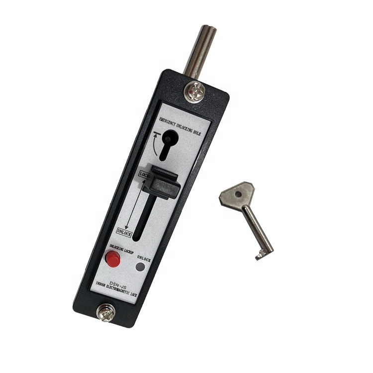
How Should Buyers Evaluate Alternative Lock Models?
Buyers should compare alternatives against the cabinet's actual mechanical and electrical requirements. Similar external dimensions do not guarantee equivalent pin travel, mounting interfaces, or operating behavior. For example, DSN DM Indoor Electromagnetic Door Lock may be considered when its documented configuration matches the intended indoor application. However, the product name alone cannot establish compatibility with a particular switchgear assembly. Procurement teams should request dimensional drawings, rated electrical data, and permitted installation positions. They should also verify material suitability and environmental limits. When evaluating substitutions, engineers must compare the complete interlocking sequence rather than one component in isolation. This approach reduces the risk of selecting a lock that fits physically but cannot perform its intended function reliably.