
How Do You Choose the Correct VPIS Rated Voltage?
Match VPIS Rated Voltage to your network and switchgear. Check nominal service voltage, coupling capacitance, frequency, and model data.
Start With the System and Equipment Data
VPIS Rated Voltage selection starts with the switchgear rating and the nominal voltage of the connected network. Record both values from the project documents before choosing an indicator. Also identify the coupling element and the system frequency. A model label gives only part of the information needed to assess the complete arrangement. Ask the supplier to confirm the intended service voltage range for the quoted configuration. Then compare that range with the actual application. Keep the accepted indicator, sensor, and voltage data together in the equipment specification.
Steps to Choose the Correct Voltage Configuration
Choose a configuration whose declared service voltage range covers the network's nominal voltage. Confirm that its equipment rating and insulation requirements suit the switchgear. Next, match the coupling element's capacitance and tolerance to the indicator's specified input requirements. Verify the operating frequency and any harness requirements for that combination. Ask the supplier to confirm the complete model code against those project data. Record the approved voltage range, sensor configuration, and drawing revision on the order. Complete the prescribed commissioning checks before accepting the installed system.
Which Voltage Values Should You Compare?
System nominal voltage identifies the network's intended operating voltage. For a three-phase network, that value generally refers to voltage between phases. The equipment rating establishes the voltage class for the switchgear and its associated insulation requirements. An indicator's declared nominal range identifies the system voltages for which its indication function applies. Consider an illustrative 10 kV network using 12 kV-class switchgear. Document both numbers and ask for confirmation of the complete sensing arrangement at that service voltage. Include the specified operating conditions and insulation requirements in the review. That gives the supplier enough information to qualify a configuration.
Voltage information to include in a selection enquiry
| Item | What to provide | What it helps establish |
|---|---|---|
| Network nominal voltage | Normal phase-to-phase value for the three-phase system | The intended service condition |
| Switchgear rated voltage | Equipment voltage class and insulation requirements | The rating of the installed assembly |
| Indicator service range | The supplier's declared range for the exact configuration | Suitability of the indication function |
| Coupling element | Model, capacitance, tolerance, and associated voltage data | Compatibility of the sensing interface |
| Frequency | The project's declared operating frequency | Compatibility with the specified sensing arrangement |
How Does Coupling Affect VPIS Rated Voltage Selection?
In a capacitive arrangement, the coupling element supplies a signal related to the monitored voltage. Its capacitance influences that signal alongside voltage and frequency. For an ideal capacitor under sinusoidal conditions, current magnitude follows I = 2πfCV. Holding frequency and voltage constant, increasing capacitance increases that current. The complete indication circuit has additional characteristics, so use the manufacturer's compatibility data to approve the combination. Compare the sensor's declared capacitance and tolerance with the indicator configuration. Include any documented harness requirements in that assessment. A replacement review should identify the installed coupling element before choosing the display.
What Does the DXN8D-12 Parameter Sheet Confirm?
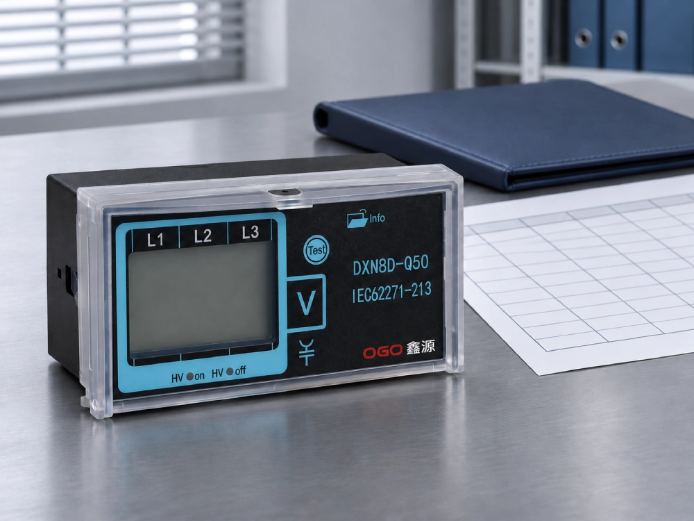
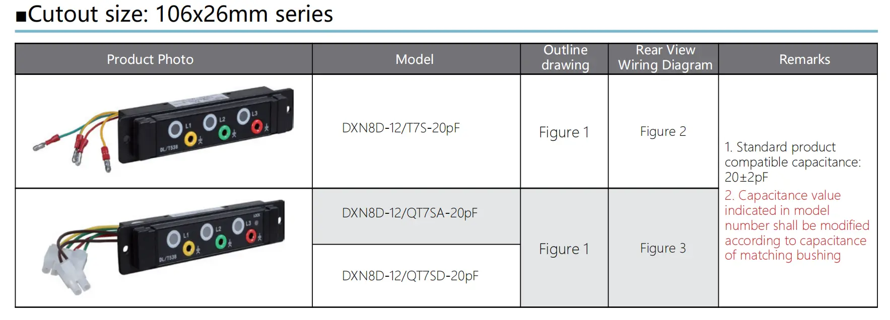
The DXN8D-12 product parameter sheet lists DXN8D-12/T7S-20pF and two QT7 variants. Its remarks specify a standard compatible capacitance of 20±2 pF. The same sheet directs configuration changes according to the matching bushing capacitance. For example, a bushing specified at 30 pF falls outside that published standard interval. Ask for an approved matching configuration before accepting that combination. Include the exact variant and bushing data with the enquiry. Request confirmation of the intended service voltage and frequency as well. Retain that confirmation with the approved product documents.
How Should You Review a Broad Model Range?
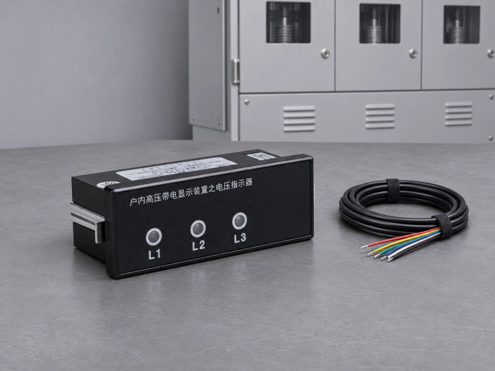
The 88×28 mm VPIS series lists model designations containing 7.2–40.5. Its parameter sheet also refers to compatible capacitance values for different voltage levels. Obtain that matching table and identify the configuration for your project voltage. Check whether the quoted code describes a family or the exact calibrated assembly. Include the coupling element, indication version, and any optional functions in the confirmation. A wide range in a model designation still requires configuration review. Record the accepted combination on the order so incoming inspection can compare the delivered unit with the specification.
How Can a Voltage-Class Change Affect Replacement?
A network modification can change the conditions seen by the sensing and indication arrangement. Revisit the selection whenever service voltage, frequency, or the coupling element changes. Start with the original approved combination and identify every proposed difference. Compare the revised operating conditions with the product's declared range and matching data. Ask whether the revised application requires another indicator configuration or sensing component. Include insulation coordination and cabinet engineering requirements in the wider equipment review. Qualified staff should complete the prescribed functional tests before commissioning the revised arrangement. Update the equipment record with the accepted configuration and test results.
What Should the Acceptance Documents Include?
Request the complete model code, nominal service range, frequency, and coupling compatibility data for the supplied assembly. Include the applicable equipment ratings and the supporting qualification documents. Test evidence should identify the configuration, test conditions, indication criteria, and observed results. Where optional contacts form part of the system, confirm their separate ratings and functions. Keep the approved drawing revision and any matching table with those records. VPIS Rated Voltage review becomes easier when each document refers to the same assembly. Complete the specified commissioning checks and retain the results with the cabinet's maintenance information.
Frequently Asked Questions
Can a 12 kV-class indicator suit a 10 kV network?
It may suit that application when the manufacturer confirms the complete configuration for the intended service conditions. A 10 kV network and 12 kV-class equipment describe different aspects of the installation. Provide both values with the sensor model, capacitance, and operating frequency. Ask for the indicator's declared service voltage range and matching requirements. Compare those documents with the cabinet design before accepting the product. For an existing installation, include the original approved specification in the review. Complete the required functional tests under the commissioning procedure after installation.
Does a 20 pF marking mean the system voltage is 20 kV?
The pF unit expresses capacitance, while kV expresses voltage. In the cited product sheet, 20 pF forms part of the matching configuration. The published standard tolerance is ±2 pF, giving an interval from 18 to 22 pF. Compare that interval with the specified coupling element and the manufacturer's compatibility instructions. Provide the network voltage separately when requesting a quotation. Include frequency and the exact product variant as well. Those values let the supplier assess the complete combination and document the configuration for the intended installation.
Can I confirm suitability by checking whether all three lamps light?
A visible response establishes only the observed indication under that particular condition. Suitability also requires the correct voltage range, sensing interface, frequency, and documented indication performance. Check the model and matching records before using the manufacturer's prescribed functional test procedure. For a replacement, compare those records with the installed sensor and cabinet schematic. Follow the site's isolation and voltage verification procedure whenever access requires it. Retain the results with the equipment documentation. Maintenance staff can then identify the approved combination and investigate indication changes.