
How Do You Read a VPIS Wiring Diagram Correctly?
Read a VPIS Wiring Diagram using the correct rear view. Check phase inputs, earth connections, sensor matching, and commissioning records.
Start With the Model and Drawing View
A VPIS Wiring Diagram identifies the connections between a voltage indicator and its specified sensing arrangement. Begin with the complete model code and the diagram revision for the supplied unit. Then find the drawing's viewing direction before comparing it with the installed device. A rear view places connections differently from the front display view. Mark the mounting orientation on a cabinet sketch and keep it beside the schematic. This prevents a left-to-right assumption from carrying into the wiring schedule. Confirm every assignment against the terminal markings before releasing the design.
Read the VPIS Wiring Diagram From the Rear
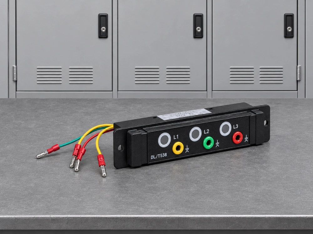
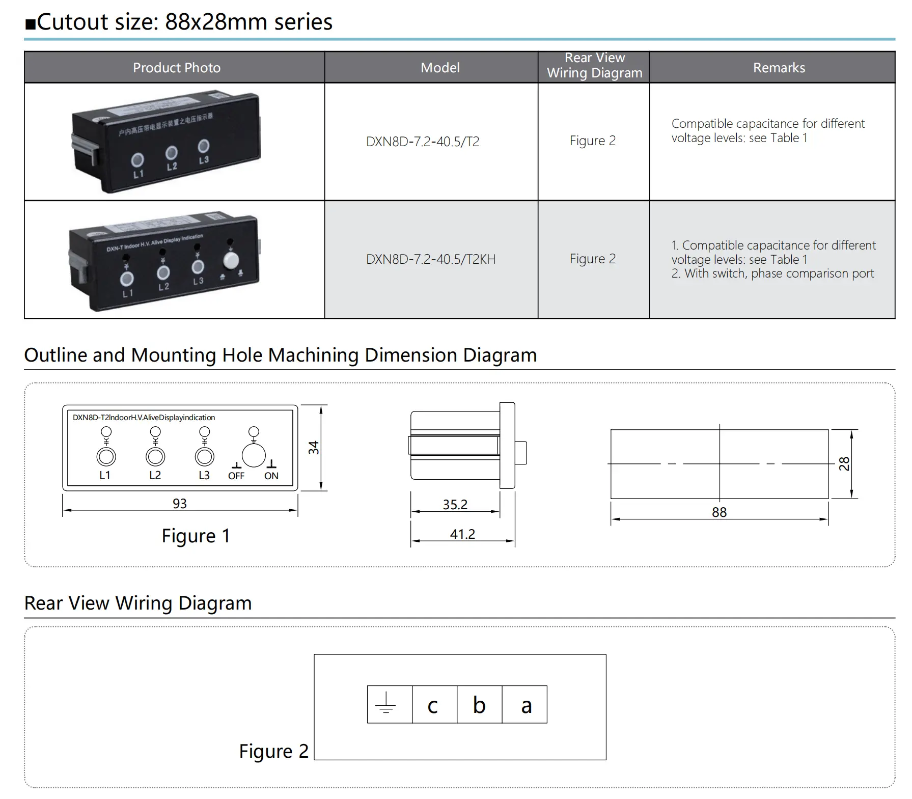
The 88×28 mm VPIS product drawing identifies Figure 2 as a rear view. From left to right, that view shows an earth symbol followed by c, b, and a. Its model table lists DXN8D-7.2-40.5/T2 and DXN8D-7.2-40.5/T2KH against that figure. Treat those assignments as specific to the illustrated configurations. When you face the installed front panel, use the approved rear view to locate each connection. Record terminal letters and wire identifiers in a connection schedule. Have the responsible engineer confirm the mapping before assembly.
Connections shown in Figure 2, viewed from the rear
| Position from left | Drawing mark | What to confirm |
|---|---|---|
| First | Earth symbol | The designated connection in the cabinet earthing arrangement |
| Second | c | The corresponding phase sensing lead and wire identifier |
| Third | b | The corresponding phase sensing lead and wire identifier |
| Fourth | a | The corresponding phase sensing lead and wire identifier |
Trace Each Phase From Sensor to Display
Build a connection record that links the primary phase, its sensing point, the harness identifier, and the indicator terminal. Confirm the associated front indication through the manufacturer's approved test method. For example, a conductor tagged as phase A should reach the assigned input in the approved circuit. If two sensing leads cross, all three lamps may still respond while the phase identification becomes incorrect. Record the verified correspondence for every phase. Where the installation requires phase comparison, use a compatible comparator and its specified procedure. Keep the comparison result separate from the basic indication test record.
Why Must the Sensing Interface Match?
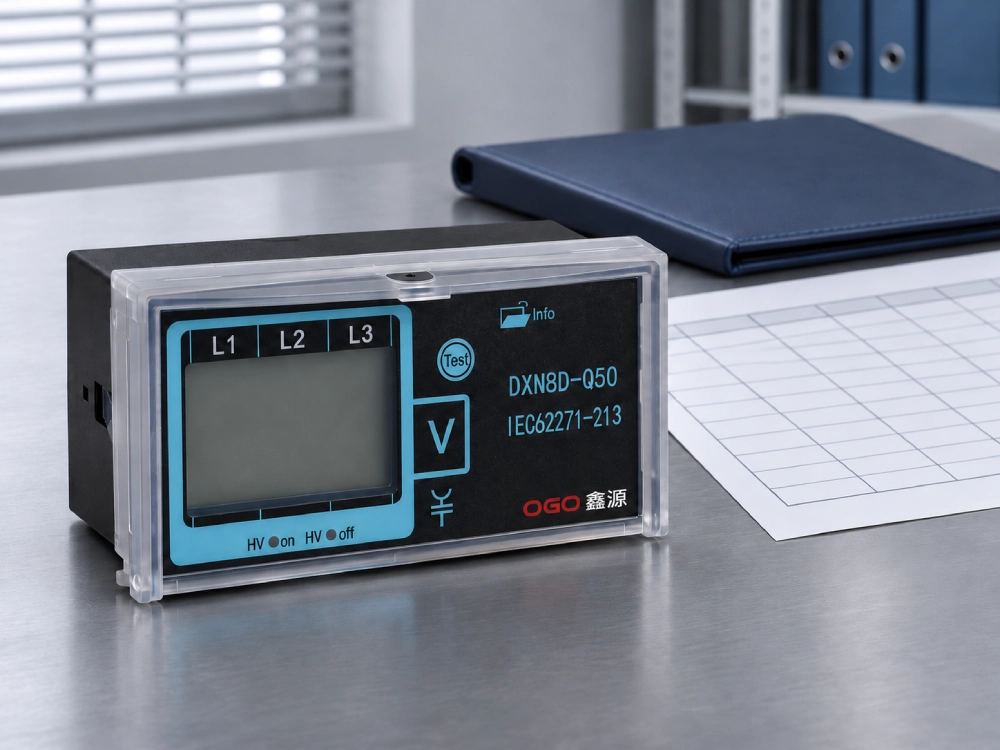
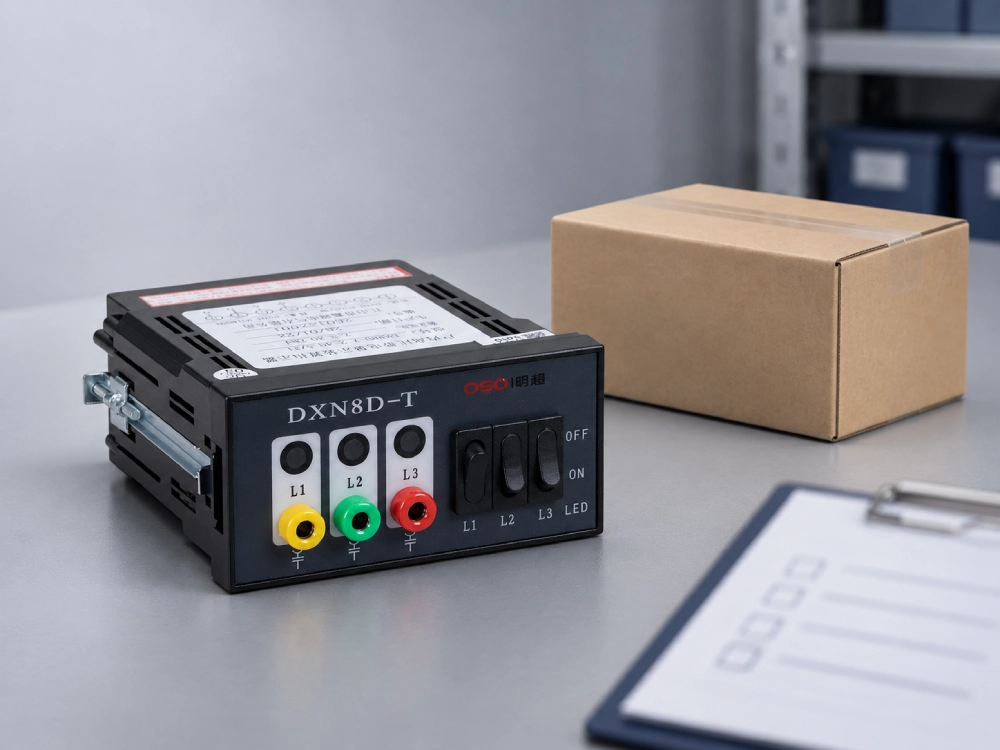
A capacitive VPIS works with a specified coupling arrangement that supplies the indication signal. The indicator, coupling element, and connection arrangement need compatible characteristics. Its 88×28 mm parameter sheet refers to a capacitance table for different voltage levels. Obtain that table for the exact proposed configuration before accepting a replacement. Compare nominal voltage, frequency, and coupling requirements with the existing cabinet documentation. For a DXN8D-12 voltage presence system, request its corresponding interface and connection documents. A matching panel opening establishes only one part of compatibility. Retain the approved electrical configuration with the purchase specification.
Identify Earth, Supply, and Optional Outputs
Read each symbol through the product's connection instructions and the cabinet schematic. An earth symbol requires the designated earth connection under those instructions. A letter beside a sensing input identifies that input's assigned function. Any separate supply or output needs its own documented rating and terminal assignment. The four positions in the illustrated rear view show phase connections and earth. Ask for a separate circuit document if the quoted version includes additional functions. Record connector orientation and any keying details in the assembly instructions. This gives production a clear reference for checking the delivered harness.
What Should a VPIS Wiring Diagram Test Record Include?
Use the approved commissioning procedure to define the test equipment, safe conditions, and acceptance criteria. Record the model code, diagram revision, and connection schedule before functional checks begin. Qualified staff should inspect terminal identification, secure connections, and the specified earth arrangement. Test each phase through the approved method and compare its indication with the expected channel. Where applicable, verify phase comparison and any separate output function. Follow the manufacturer's instructions before applying insulation tests to connected electronics. Keep observed results alongside expected results so later maintenance can identify changes in the installed system.
How Can You Investigate an Unexpected Display?
Start by recording which indicators respond and when the symptom occurs. A single dark channel can involve its sensing lead, connection, coupling element, or indicator channel. Several dark channels can involve a shared connection or a wider sensing issue. These are investigation paths that qualified staff should assess through the approved diagnostic procedure. Compare the actual wiring with the diagram before replacing components. Include model compatibility and recent harness changes in the review. Before access, complete isolation and voltage verification under the site's approved procedure. Resolve unexpected indication before relying on the system for an operational decision.
Frequently Asked Questions
Can I identify the connections by wire color?
Use the terminal markings and approved wiring schedule to identify each connection. A color can assist assembly when the documented harness specifies it, but the assignment must match that harness. Replacement products can use different connector layouts or lead identification. Record both the wire identifier and destination terminal during a retrofit. Check the drawing's viewing direction and compare the actual device markings. Then verify each channel through the manufacturer's approved procedure. This approach lets maintenance staff trace a connection even when a later harness uses different insulation colors.
Do three illuminated lamps prove the phase mapping is correct?
Three responsive lamps show that the channels produce an indication under the observed conditions. Phase mapping requires a separate check of which sensing point feeds each channel. Swapped leads can preserve three visible indications while changing the association with the primary phases. Trace the wire identifiers against the approved schematic and verify the channels through the specified procedure. If the project requires phase concordance, use the compatible instrument and instructions for that task. Record the results by circuit and phase so the commissioning record shows exactly what the team verified.
Can I reuse the old harness when replacing the indicator?
Compare the proposed unit with the existing harness before approving reuse. Check connector type, keying, contact assignment, insulation condition, and the sensing interface requirements. Include cable specifications and permitted installation conditions from the manufacturer's documents. A connector that fits physically still needs an assignment check against the exact replacement diagram. If an adapter forms part of the approved retrofit, retain its drawing with the maintenance record. Qualified staff should complete the required channel checks after installation. Update the connection schedule whenever the accepted replacement changes terminal positions or wire identifiers.